315
Chapter 9 Specifications
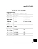
N2266A 40-Channel MUX Module
4
9
N2266A 40-Channel MUX Module
INPUT CHARACTERISTICS
Total Channels:
80 1-wire; or 40 2-wire; or dual 20 2-wire; or 20 4-wire
Maximum Switching
Voltage:
Terminal-Terminal or
Terminal-Chassis:
200 V, dc or peak AC Resist.
Maximum Switching
Current:
Per Channel:
Per Module:
0.5 A, dc or peak AC Resist.
1 A, dc or peak AC Resist.
Maximum Switching
Power:
Per Channel:
Per Module:
10 W dc or peak AC Resist.
20 W dc or peak AC Resist.
Thermal Offset:
Per Channel:
50
µ
V differential or single-ended
Initial Closed Channel
Resistance:
< 1
Ω
Relay Life:
@1V/1mA:
10
9
Maximum Scan Rate
350 Chans/sec
DC CHARACTERISTICS
Open Channel,
Channel-Channel:
(with 1 channel closed)
< (40
o
C, 50% RH):
< (40
o
C, 80% RH):
> 10
10
Ω
> 10
9
Ω
HI-LO:
(with 1 channel closed)
< (40
o
C, 50% RH):
< (40
o
C, 80% RH):
> 10
10
Ω
> 10
9
Ω
Channel-Chassis:
(with 1 channel closed)
< (40
o
C, 50% RH):
< (40
o
C, 80% RH)”
> 10
10
Ω
> 10
9
Ω
Summary of Contents for Agilent 3499A
Page 13: ...1 1 Quick Start ...
Page 27: ...2 2 Front Panel Operation ...
Page 55: ...3 3 System Overview ...
Page 77: ...4 4 Features and Functions ...
Page 113: ...5 5 Remote Interface Reference ...
Page 164: ...164 5 ...
Page 165: ...6 6 Error Messages ...
Page 173: ...7 7 Plug in Modules ...
Page 256: ...256 Chapter 7 Plug in Modules 44475A Breadboard Module 7 ...
Page 261: ...261 Chapter 7 Plug in Modules 44476B Microwave Switch Module 4 7 The 44476B is shown below ...
Page 286: ...286 Chapter 7 Plug in Modules Terminals and Connections Information 7 ...
Page 288: ...288 7 ...
Page 289: ...8 8 Application Programs ...
Page 299: ...9 9 Specifications ...
Page 343: ...343 Chapter 9 Specifications 44475A Breadboard Module 4 9 ...


