341
Chapter 9 Specifications
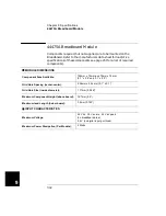
44474A 16-Bit Digital I/O Module
4
9
44474A 16-Bit Digital I/O Module
I/O LINES
Number of Bits:
16
Maximum Voltage:
Line-Chassis:
+30 V dc
Output Characteristics:
Vout (high):
Vout (low):
I (low):
≥
2.4 V @ I
≤
8 mA output
≤
0.4 V @ I
≤
16 mA input
= 125 mA @ Vout (low)
≤ 1.25
V
fused at 250 mA
Input Characteristics:
Vin (high):
Vin (low):
≥
2.0 V
≤
0.8 V
HANDSHAKE LINES
Maximum Voltage:
Line-Chassis:
+5 V dc
Output Characteristics:
Vout (high):
Vout (low):
≥
2.4 V @ I
≤
400
µ
A output
≤
0.5 V @ I
≤
2 mA input
Input Characteristics:
Vin (high):
Vin (low):
≥
2.0 V
≤
0.8 V
External Increment (EI):
a
a.
Both EI and CC lines are used for external controlled scanning. The 3499A/B/C will advance to the next channel in
the scan list on the falling edge of EI pulse.
Minimum TTL Pulse Width:
0.25
µ
s
Channel Closed (CC):
b
b.
When the next channel closes, the 44474A outputs a CC pulse to trigger the voltmeter.
Minimum TTL Pulse Width:
10
µ
s
Summary of Contents for Agilent 3499A
Page 13: ...1 1 Quick Start ...
Page 27: ...2 2 Front Panel Operation ...
Page 55: ...3 3 System Overview ...
Page 77: ...4 4 Features and Functions ...
Page 113: ...5 5 Remote Interface Reference ...
Page 164: ...164 5 ...
Page 165: ...6 6 Error Messages ...
Page 173: ...7 7 Plug in Modules ...
Page 256: ...256 Chapter 7 Plug in Modules 44475A Breadboard Module 7 ...
Page 261: ...261 Chapter 7 Plug in Modules 44476B Microwave Switch Module 4 7 The 44476B is shown below ...
Page 286: ...286 Chapter 7 Plug in Modules Terminals and Connections Information 7 ...
Page 288: ...288 7 ...
Page 289: ...8 8 Application Programs ...
Page 299: ...9 9 Specifications ...
Page 343: ...343 Chapter 9 Specifications 44475A Breadboard Module 4 9 ...


