347
Chapter 9 Specifications
44478A/B 1.3 GHz Dual 4-to-1 MUX Modules
4
9
44478A /B 1.3 G H z D u al 4-to-1 M U X M odu les
Specifications in the table describe the modules’ warranted performance
over the temperature range 0º to 55º C. Information marked by the
“Typical” designation is helpful in applying the modules, but is non-
warranted information
.
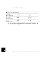
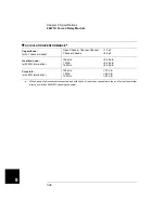
INPUT CHARACTERISTICS
Total Channels:
Dual 4 Chans
Maximum Voltage:
Any Center/Shield to Any
Other Center/Shield/
Chassis:
42 V dc + ac peak
Maximum Current:
Per Channel or Common:
1 A dc, or ac rms
Maximum Power:
Per Channel or Common:
Each Resistive Termination:
24 W, 24 VA or 44 dBm
0.25 W, 0.25 VA or 24 dBm
Characteristic Impedance:
44478A:
44478B:
50
Ω
75
Ω
Relay Life (Typical):
With No Load:
At Maximum Rated Power:
5 x 10
6
operations
10
5
operations
Maximum Scan Rate:
a
43 Chans/sec
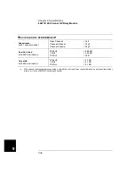
DC PERFORMANCE
Thermal Offset:
Per Channel:
< 6
µ
V (< 2
µ
V, Typical)
Initial Closed Channel
Resistance:
< 1
Ω
Insulation Resistance
(any terminal to any terminal)
≤
(40
o
C, 95% RH):
≤
(25
o
C, 40% RH):
> 10
8
Ω
> 10
10
Ω
(Typical)
a.
Using the 44474A external increment & channel closed, display off.
Summary of Contents for Agilent 3499A
Page 13: ...1 1 Quick Start ...
Page 27: ...2 2 Front Panel Operation ...
Page 55: ...3 3 System Overview ...
Page 77: ...4 4 Features and Functions ...
Page 113: ...5 5 Remote Interface Reference ...
Page 164: ...164 5 ...
Page 165: ...6 6 Error Messages ...
Page 173: ...7 7 Plug in Modules ...
Page 256: ...256 Chapter 7 Plug in Modules 44475A Breadboard Module 7 ...
Page 261: ...261 Chapter 7 Plug in Modules 44476B Microwave Switch Module 4 7 The 44476B is shown below ...
Page 286: ...286 Chapter 7 Plug in Modules Terminals and Connections Information 7 ...
Page 288: ...288 7 ...
Page 289: ...8 8 Application Programs ...
Page 299: ...9 9 Specifications ...
Page 343: ...343 Chapter 9 Specifications 44475A Breadboard Module 4 9 ...


