98
Chapter 4 Features and Functions
Digital I/O Operation
4
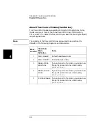
About Flow Control Modes (Handshake)
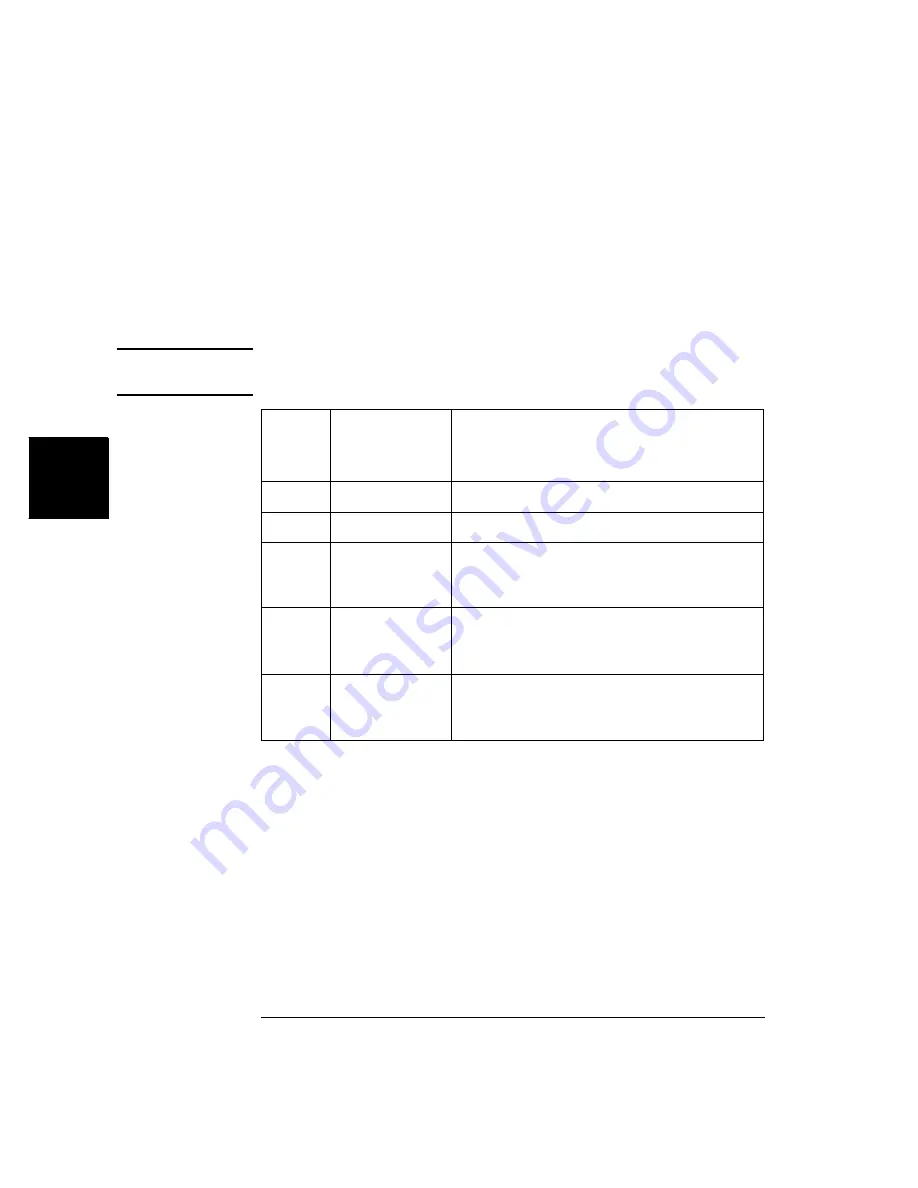
Five flow control modes are available for Digital I/O operations. Some
modes use one or more of the three flow control lines: I/O Direction,
PFLG, and PCTL. Select the flow control you need for your digital input/
output applications.
Note
The polarity of the flow control lines is assumed to be positive (the
default) in the following diagrams and discussions.
Mode
Number
Handshake
Mode
Definition
Notes
1
Static mode #1
Default handshake mode.
2 Static
mode
#2
Read what was written.
3 Read
or
Write
and strobe
If you set a port to this mode, you cannot use
the port in a scan list or use card pairing
(
ROUTe:CPAir
).
4 Read
and
write
strobe
If you set a port to this mode, you cannot use
the port in a scan list or use card pairing
(
ROUTe:CPAir
).
5
Full handshake
If you set a port to this mode, you cannot use
the port in a scan list or use card pairing
(
ROUTe:CPAir
).
Summary of Contents for Agilent 3499A
Page 13: ...1 1 Quick Start ...
Page 27: ...2 2 Front Panel Operation ...
Page 55: ...3 3 System Overview ...
Page 77: ...4 4 Features and Functions ...
Page 113: ...5 5 Remote Interface Reference ...
Page 164: ...164 5 ...
Page 165: ...6 6 Error Messages ...
Page 173: ...7 7 Plug in Modules ...
Page 256: ...256 Chapter 7 Plug in Modules 44475A Breadboard Module 7 ...
Page 261: ...261 Chapter 7 Plug in Modules 44476B Microwave Switch Module 4 7 The 44476B is shown below ...
Page 286: ...286 Chapter 7 Plug in Modules Terminals and Connections Information 7 ...
Page 288: ...288 7 ...
Page 289: ...8 8 Application Programs ...
Page 299: ...9 9 Specifications ...
Page 343: ...343 Chapter 9 Specifications 44475A Breadboard Module 4 9 ...


