W
WWWWWWWWWWWWWWWWWWWWWWWWWWWWWWWWWWWWWWWWWWWWWWWWWWWWWWWWWWWWWWWW
AZ
SWITCH
on
OFF
(:DIAG:SERV:BUS:AZER
{OFF|ON|0|1})
T
oggles
the
auto
zero
switch
on
and
o.
W
WWWWWWWWWWWWWWWWWWWWWWWWWWWWWWWWWWWWWWWWW
WAIT
COUNT
(:DIAG:SERV:BUS:WAIT
<numeric>)
Sets
the
wait
count
to
specify
the
wait
time
in
the
DC
bus
measurement.
The
wait
count
is
an
integer
from
2
to
32767.
When
the
wait
count
is
N,
the
analyzer
waits
N
*
12.5
sec
before
each
DC
bus
measurement.
Bus
Measurement
In
this
service
mode
,
the
analyzer
measures
and
displays
the
signal
voltage
or
frequency
at
the
selected
bus
node
.
This
service
mode
allows
you
to
check
the
circuit
operation
by
monitoring
the
circuit
signal
without
accessing
the
inside
of
the
analyzer
.
The
analyzer
has
33
bus
nodes
for
this
service
mode
.
Of
these
,
26
bus
nodes
are
for
DC
voltage
measurement.
These
nodes
are
connected
to
the
A/D
converter
in
the
A6
receiver
IF
through
the
DC
Bus
,
a
single
multiplexer
line
with
twenty-six
channels
.
The
other
7
bus
nodes
are
for
frequency
measurement.
These
nodes
are
connected
to
the
frequency
bus
timer
in
the
A1
CPU
through
the
frequency
bus
,
a
single
multiplexer
line
with
7
channel.
Each
of
the
DC
bus
nodes
and
the
frequency
bus
nodes
is
described
in
the
DC
Bus
Nodes
and
Frequency
Bus
Nodes
in
this
section.
Bus
Measurement
Procedure
Use
this
procedure
to
perform
the
bus
measurement.
1.
Press
4
Preset
5
to
initialize
the
analyzer
.
2.
Set
the
analyzer
controls
to
the
settings
that
you
desire
to
observe
in
the
bus
measurement.
3.
Press
4
System
5 ,
NNNNNNNNNNNNNNNNNNNNNNNNNNNNNNNNNNNNNN
SERVICE
MENU
,
NNNNNNNNNNNNNNNNNNNNNNNNNNNNNNNNNNNNNNNNN
SERVICE
MODES
,
NNNNNNNNNNNNNNNNNNNNNNNNNN
BUS
MEAS
to
display
the
bus
measurement
menu.
4.
Select
the
desired
bus
node
as
follows:
If
a
DC
bus
measurement
is
desired,
press
NNNNNNNNNNNNNNNNNNNNNNNNNNNNNNNNNNNNNN
DC
BUS
[OFF]
.
Then
enter
a
node
number
between
1
and
26.
If
a
frequency
bus
measurement
is
desired,
press
N
NNNNNNNNNNNNNNNNNNNNNNNNN
FREQ
BUS
.
Then
enter
a
node
number
between
1
and
7.
5.
Press
NNNNNNNNNNNNNNNNNNNNNNNNNNNNNNNNNNNNNNNNNNNNNNN
BUS
MEAS
on
OFF
to
activate
the
bus
measurement.
The
menu
changes
to
NNNNNNNNNNNNNNNNNNNNNNNNNNNNNNNNNNNNNNNNNNNNNNN
BUS
MEAS
ON
off
.
The
DC
or
frequency
bus
measurement
value
is
displayed
in
the
marker
value
.
See
the
Bus
Measurement
V
alues
section.
6.
Observe
the
bus
measurement
trace
and
marker
value
.
7.
Press
4
Preset
5
to
exit
the
bus
measurement.
T
o
change
the
bus
node
to
another
node
,
repeat
the
steps
above
.
Both
the
DC
bus
and
the
frequency
bus
can
be
monitored
simultaneously
.
This
helps
when
observing
the
relationship
between
the
V
CO
tuning
voltage
and
the
V
CO
output
frequency
of
the
fractional
N
oscillator
.
See
the
Bus
Measurement
V
alues
section.
10-22
Service
K
ey
Menus
Summary of Contents for Agilent 4396B
Page 10: ......
Page 32: ......
Page 43: ...Figure 2 7 CAL OUT Level Adjustment Location Adjustments and Correction Constants 2 11 ...
Page 46: ...Figure 2 10 Comb Generator Output 2 14 Adjustments and Correction Constants ...
Page 62: ...Figure 2 26 Final Gain Adjustment Location 2 30 Adjustments and Correction Constants ...
Page 76: ...Figure 3 1 Troubleshooting Organization 3 2 T roubleshooting ...
Page 84: ......
Page 90: ...Figure 5 1 Power Supply Lines Simpli ed Block Diagram 5 2 Power Supply T roubleshooting ...
Page 107: ...Figure 5 12 Power Supply Block Diagram 1 Power Supply T roubleshooting 5 19 ...
Page 108: ...Figure 5 13 Power Supply Block Diagram 2 5 20 Power Supply T roubleshooting ...
Page 109: ...Figure 5 14 Power Supply Block Diagram 3 Power Supply T roubleshooting 5 21 ...
Page 110: ......
Page 112: ...Figure 6 1 Digital Control Group Simpli ed Block Diagram 6 2 Digital Control T roubleshooting ...
Page 124: ......
Page 126: ...Figure 7 1 Source Group Block Diagram 7 2 Source Group T roubleshooting ...
Page 160: ...Figure 8 1 Receiver Group Simpli ed Block Diagram 8 2 Receiver Group T roubleshooting ...
Page 168: ......
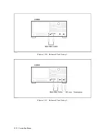
Page 184: ...Figure 10 6 External Test Setup 1 Figure 10 7 External Test Setup 2 10 10 Service Key Menus ...
Page 185: ...Figure 10 8 External Test Setup 3 Figure 10 9 External Test Setup 4 Service Key Menus 10 11 ...
Page 226: ...Figure 11 3 Power Supply Functional Group Simpli ed Block Diagram 11 6 Theory of Operation ...
Page 231: ...Figure 11 5 Digital Control Group Simpli ed Block Diagram Theory of Operation 11 11 ...
Page 235: ...Figure 11 6 Source Simpli ed Block Diagram Theory of Operation 11 15 ...
Page 244: ...Figure 11 7 Receiver Simpli ed Block Diagram 11 24 Theory of Operation ...
Page 249: ...Figure IDC5S11001 here Figure 11 8 4396B Source Group Block Diagram Theory of Operation 11 29 ...
Page 254: ...Figure 12 1 Top View Major Assemblies 12 4 Replaceable Parts ...
Page 290: ...Figure 12 36 Main Frame Assembly Parts 17 19 12 40 Replaceable Parts ...
Page 294: ......
Page 308: ......
Page 311: ...Figure C 1 Power Cable Supplied Power Requirement C 3 ...
Page 312: ......
Page 324: ......

