T
able
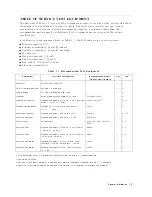
1-1.
Recommended
T
est
Equipment
(continued)
Equipment
Critical
Specications
Recommended
Model/
Agilent
P
art
Number
Qty
Use
1
Signal
Generator
Frequency
Range:
100
kHz
to
2.14
GHz,
SSB
Phase
Noise
at
1
kHz
oset:
<
0110
dBc/Hz,
SSB
Phase
Noise
at
10
kHz
oset:
<
0119
dBc/Hz,
Harmonics:
<
030
dBc
8663A
or
8642B
1
P
,
A
Signal
Generator
Frequency
Range:
100
kHz
to
1.82
GHz
8663A
or
8642B
1
P
,
A
Oscilloscope
54600B
1
A
Oscilloscope
Probe
Impedance:
1
M
10431A
1
A
Step
Attenuator
1
Attenuation
Range:
0
dB
to
70
dB
,
Step:
10
dB
,
VSWR:
1.02
8496A/G
Option
001
and
H60
2
1
P
Step
Attenuator
1
Attenuation
Range:
0
dB
to
10
dB
,
Step:
1
dB
,
VSWR:
1.02
8494A/G
Option
001
and
H60
3
1
P
Attenuator/Switch
Driver
No
substitute
11713A
4
1
P
50
Type-N
Calibration
Kit
No
substitute
85032B
1
P
T/R
T
est
Sets
Frequency
Range:
300
kHz
to
1.8
GHz,
Directivity:
40
dB
85044A
1
P
50
MHz
Low
P
ass
Filter
Rejection
at
75
MHz:
60
dB
PN
0955-0306
1
P
T
ermination
50
T
ermination
909C
Opt
012
or
part
of
85032B
5
3
P
,
A,
T
6
dB
Fixed
Attenuation
50
,
N(m)-N(f)
8491A
Opt
006
2
P
6
dB
Fixed
Attenuation
50
,
N(m)-N(f),
VSWR
1.015
8491A
Opt
006
&
Opt
H60
6
2
P
Two-W
ay
P
ower
Splitter
Frequency
Range:
100
kHz
to
1.8
GHz,
Output
Tracking:
0.15
dB
11667A
1
P
,
A,
T
Cables
Type-N
cable
,
50
11500B
or
part
of
11851B
7
4
P
,
A,
T
RF
cable
kit
11851B
1
P
,
A
BNC
cable
,
61
cm,
50
PN
8120-1839
1
P
,
A,
T
BNC
cable
,
122
cm,
50
PN
8120-1840
2
P
,
A,
T
GPIB
cable
10833A/B/C
3
A
1
Calibration
values
at
50
MHz
are
required
in
the
tests
.
See
the
Calibration
Data
R
equired
for
Step
Attenuators
in
P
erformance
T
est
Manual
.
2
An
8496A/G
step
attenuator
with
required
low
VSWR
(
1.02)
can
be
purchased
by
specifying
option
H60.
3
An
8494A/G
step
attenuator
with
required
low
VSWR
(
1.02)
can
be
purchased
by
specifying
option
H60.
4
Required
when
an
8494G
or
8496G
step
attenuator
is
used
in
the
tests
.
5
The
85032B
includes
a
type-N(m)
50
termination.
6
An
8491A
Opt.
006
xed
attenuator
with
required
low
VSWR
(
1.015)
can
be
purchased
by
specifying
Opt.
H60.
7
The
11851B
includes
three
N(m)-N(m)
cables
of
61
cm
and
a
N(m)-N(m)
cable
of
88
cm.
1-4
General
Information
Summary of Contents for Agilent 4396B
Page 10: ......
Page 32: ......
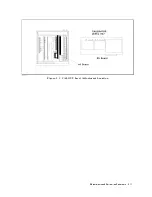
Page 43: ...Figure 2 7 CAL OUT Level Adjustment Location Adjustments and Correction Constants 2 11 ...
Page 46: ...Figure 2 10 Comb Generator Output 2 14 Adjustments and Correction Constants ...
Page 62: ...Figure 2 26 Final Gain Adjustment Location 2 30 Adjustments and Correction Constants ...
Page 76: ...Figure 3 1 Troubleshooting Organization 3 2 T roubleshooting ...
Page 84: ......
Page 90: ...Figure 5 1 Power Supply Lines Simpli ed Block Diagram 5 2 Power Supply T roubleshooting ...
Page 107: ...Figure 5 12 Power Supply Block Diagram 1 Power Supply T roubleshooting 5 19 ...
Page 108: ...Figure 5 13 Power Supply Block Diagram 2 5 20 Power Supply T roubleshooting ...
Page 109: ...Figure 5 14 Power Supply Block Diagram 3 Power Supply T roubleshooting 5 21 ...
Page 110: ......
Page 112: ...Figure 6 1 Digital Control Group Simpli ed Block Diagram 6 2 Digital Control T roubleshooting ...
Page 124: ......
Page 126: ...Figure 7 1 Source Group Block Diagram 7 2 Source Group T roubleshooting ...
Page 160: ...Figure 8 1 Receiver Group Simpli ed Block Diagram 8 2 Receiver Group T roubleshooting ...
Page 168: ......
Page 184: ...Figure 10 6 External Test Setup 1 Figure 10 7 External Test Setup 2 10 10 Service Key Menus ...
Page 185: ...Figure 10 8 External Test Setup 3 Figure 10 9 External Test Setup 4 Service Key Menus 10 11 ...
Page 226: ...Figure 11 3 Power Supply Functional Group Simpli ed Block Diagram 11 6 Theory of Operation ...
Page 231: ...Figure 11 5 Digital Control Group Simpli ed Block Diagram Theory of Operation 11 11 ...
Page 235: ...Figure 11 6 Source Simpli ed Block Diagram Theory of Operation 11 15 ...
Page 244: ...Figure 11 7 Receiver Simpli ed Block Diagram 11 24 Theory of Operation ...
Page 249: ...Figure IDC5S11001 here Figure 11 8 4396B Source Group Block Diagram Theory of Operation 11 29 ...
Page 254: ...Figure 12 1 Top View Major Assemblies 12 4 Replaceable Parts ...
Page 290: ...Figure 12 36 Main Frame Assembly Parts 17 19 12 40 Replaceable Parts ...
Page 294: ......
Page 308: ......
Page 311: ...Figure C 1 Power Cable Supplied Power Requirement C 3 ...
Page 312: ......
Page 324: ......


