2-8
Using the Multi-Wavelength Meter
Displaying Wavelength and Power
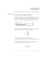
where,
n
is the number of laser lines included in the measurement.
P
i
is the peak power of an individual laser line. Power units are in Watts (lin-
ear).
To display average wavelength and total power
• Press the
Avg WL
key.
Measuring lasers between 700 nm and 1200 nm
After the
Preset
key is pressed, the input wavelength range is limited to mea-
suring lasers between 1200 nm and 1650 nm. This prevents the accidental dis-
play of spurious signals that may not exist. You can easily expand the input
range to the full 700 nm to 1650 nm range, however you should learn how to
identify spurious signals.
Spurious signals below 1200 nm may be displayed whenever low-power laser
lines (power levels near the Agilent 86120B’s specified sensitivity) are present
at the input. For example, a low-power laser line at 1550 nm has a second har-
monic line at 775 nm. If this second harmonic is above the peak threshold level
relative to the fundamental line, it is considered a peak. Its displayed power
level may be
greater
than that of the fundamental because the amplitude cor-
rection at 775 nm is much greater (by about 15 dB) than that at 1550 nm (the
interferometer is less sensitive at 775 nm).
You can also avoid displaying this second harmonic line by reducing the peak
threshold below its preset value. Because the peak threshold level is used to
determine which signals are to be displayed
before
amplitude corrections are
applied, the harmonic will be eliminated.
Refer to “Defining Laser-Line Peaks”
.
To use the full wavelength range
1
Press the
Setup
key.
2
Press the
WL LIM
softkey.
3
Press
LIM OFF
to remove the limits on wavelength range. All responses in the full
700 nm to 1650 nm range are now displayed.
Summary of Contents for Agilent 86120B
Page 1: ...Agilent 86120B Multi Wavelength Meter User s Guide ...
Page 11: ...Contents 3 Contents Power Cords 8 16 Agilent Technologies Service Offices 8 18 ...
Page 12: ......
Page 38: ......
Page 68: ......
Page 100: ...4 18 Programming Monitoring the Instrument ...
Page 132: ......
Page 230: ......
Page 248: ...8 6 Reference Menu Maps Delta On Menu Delta Off Menu ...
Page 250: ...8 8 Reference Menu Maps System Setup Menu ...
Page 268: ......


