6-5
Performance Tests
Test 3. Polarization Dependence
Test 3. Polarization Dependence
Description
Polarization Dependence is verified using the following devices:
• 1310 nm and 1550 nm DFB lasers
• Optical attenuator
• Agilent 11896A Polarization Controller
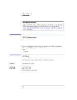
C A U T I O N
Do not 18 dBm source power. The Agilent 86120B’s input circuitry can
be damaged when total input power exceeds 18 dBm.
Procedure
Perform the following procedure first using the 1310 nm laser and then repeat
the steps using the 1550 nm laser.
1
Turn on the lasers and allow them to warm up.
2
Set the polarization controller to a scan rate of 5.
3
On the Agilent 86120B, press the
Preset
key.
4
Connect the laser’s optical output to the polarization controller’s optical input.
5
Connect the polarization controller’s optical output to the Agilent 86120B
being tested.
6
Set the polarization controller to autoscan.
7
On the Agilent 86120B, press
Peak WL
,
Appl’s
, and then
DRIFT
. Press
MAX-MIN
so
that both
MAX
and
MIN
in the softkey label are highlighted. The display shows
the total drift since the drift measurement was started.
8
Wait five minutes, read the peak amplitude drift from the Agilent 86120B, and
compare with the specification listed in
Chapter 7, “Specifications and
.
Summary of Contents for Agilent 86120B
Page 1: ...Agilent 86120B Multi Wavelength Meter User s Guide ...
Page 11: ...Contents 3 Contents Power Cords 8 16 Agilent Technologies Service Offices 8 18 ...
Page 12: ......
Page 38: ......
Page 68: ......
Page 100: ...4 18 Programming Monitoring the Instrument ...
Page 132: ......
Page 230: ......
Page 248: ...8 6 Reference Menu Maps Delta On Menu Delta Off Menu ...
Page 250: ...8 8 Reference Menu Maps System Setup Menu ...
Page 268: ......

