26
Agilent E1412A Multimeter Application Information
Loading Errors
(dc volts)
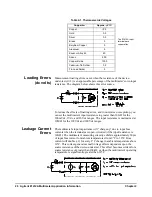
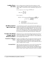
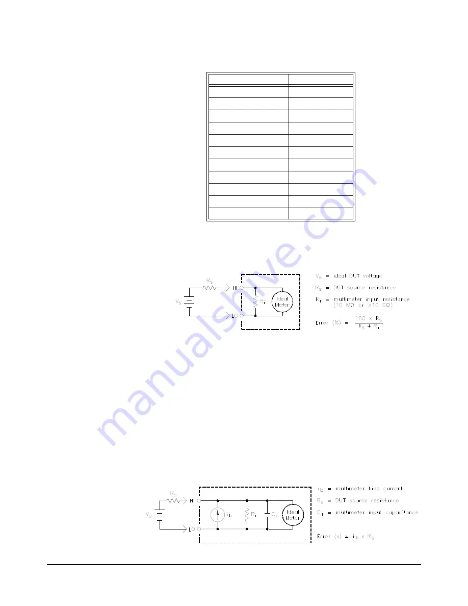
Measurement loading errors occur when the resistance of the device-
under-test (
DUT
) is an appreciable percentage of the multimeter's own input
resistance. The diagram below shows this error source.
To reduce the effects of loading errors, and to minimize noise pickup, you
can set the multimeter's input resistance to greater than 10G
for the
100mVdc, 1Vdc, and 10Vdc ranges. The input resistance is maintained at
10M
for the 100Vdc and 300Vdc ranges.
Leakage Current
Errors
The multimeter's input capacitance will “charge up” due to input bias
currents when the terminals are open-circuited (if the input resistance is
10G
). The multimeter's measuring circuitry exhibits approximately 30pA
of input bias current for ambient temperatures from 0°C to 30°C. Bias
current will double (
2) for every 8°C change in ambient temperature above
30°C. This current generates small voltage offsets dependent upon the
source resistance of the device-under-test. This effect becomes evident for a
source resistance of greater than 100k
, or when the multimeter's operating
temperature is significantly greater than 30°C.
Table 2-1. Thermoelectric Voltages
Copper-to-
Approx.
V/
C
Copper
<0.3
Gold
0.5
Silver
0.5
Brass
3
Beryllium Copper
5
Aluminum
5
Kovar or Alloy 42
40
Silicon
500
Copper-Oxide
1000
Cadmium-Tin Solder
0.2
Tin-Lead Solder
5
The E1412A input
terminals are
copper alloy.
Summary of Contents for Agilent E1412A
Page 2: ......
Page 10: ...8 Contents Notes...
Page 14: ...12 Notes...
Page 15: ...13 Notes...
Page 16: ...14 Notes...
Page 26: ...24 Agilent E1412A Multimeter Module Setup Chapter 1 Notes...
Page 194: ...192 Agilent E1412A Multimeter Error Messages Appendix B Notes...
Page 201: ...Index 199 Index Agilent E1412A User s Manual and SCPI Programming Guide...


