46
Agilent E1412A Multimeter Application Information
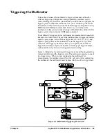
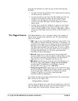
Triggering the multimeter is a multi-step process that offers triggering
flexibility.
1. You must configure the multimeter for the measurement by selecting
the function, range, resolution, etc.
2. You must specify the source from which the multimeter will accept
the trigger. The multimeter will accept a BUS trigger from the
VXIbus, an external trigger from the front panel “Trig” BNC
connector or an immediate trigger from the multimeter's internal
trigger system.
3. You must make sure that the multimeter is ready to accept a trigger
from the specified trigger source (this is called the
wait-for-trigger
state) by issuing a
READ?
or
INIT
command. A
MEASure
command
always uses an immediate trigger (see the flow chart in Figure 2-1 on
page
The Trigger Source
The
TRIGger:SOURce <
source
>
command configures the multimeter's
trigger system to respond to the specified source. The following trigger
sources are available:
•
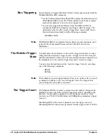
BUS:
Trigger source is the GPIB Group Execute Trigger (GET) or the
*TRG
common command. Within the 75000 Series C mainframes, the
instrument whose trigger source is “
BUS
” and was the last instrument
addressed to listen will respond to the GPIB Group Execute Trigger.
The
*TRG
command differs from GET because it is sent to a specific
instrument not a group of instruments. NOTE: B-size controllers do
not support the BUS trigger (e.g., E1306A command module,
E1300/E1301A B-size mainframes).
•
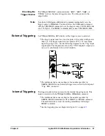
EXTernal:
Trigger source is the multimeter's external trigger BNC
connector (labeled “Trig” on the front panel). A falling (negative-going)
edge of the input signal triggers the multimeter. The external pulse
signal must be >1
s, +5V maximum to 0V (TTL levels).
•
IMMediate:
Internal trigger is always present. If the multimeter is in
the wait-for-trigger state (
INITiate
),
TRIGger:SOURce IMMediate
sends the trigger. The
MEASure
and
CONFigure
commands
automatically set the trigger source to
IMMediate
.
•
TTLTrg0
through
TTLTrg7:
Trigger source is the VXIbus TTL trigger
lines. The multimeter is triggered on the falling (negative- going) edge
of a TTL input signal. NOTE: B-size controllers do not support
VXIbus TTL triggers (e.g., E1306A Command Module,
E1300/E1301B B-Size Mainframes).
For example, the following program statement selects the external trigger
BNC connector as the trigger source.
TRIGger:SOURce EXTernal
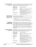
You can change the trigger source only when the multimeter is in the idle
state. Attempting to change the trigger source while the multimeter is in the
wait-for-trigger state will generate the “Settings conflict” error.
Summary of Contents for Agilent E1412A
Page 2: ......
Page 10: ...8 Contents Notes...
Page 14: ...12 Notes...
Page 15: ...13 Notes...
Page 16: ...14 Notes...
Page 26: ...24 Agilent E1412A Multimeter Module Setup Chapter 1 Notes...
Page 194: ...192 Agilent E1412A Multimeter Error Messages Appendix B Notes...
Page 201: ...Index 199 Index Agilent E1412A User s Manual and SCPI Programming Guide...

