Agilent E1412A Multimeter Application Information
49
Example: Setting the
Trigger Count
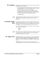
In the following example, one DC voltage measurement is made each time the
multimeter's external trigger BNC connector is pulsed low. After 10 external
triggers are received, the multimeter returns to the idle state.
dimension array
Dimension computer array.
CONF:VOLT:DC
Function: DC voltage.
TRIG:SOUR EXT
Trigger source is external BNC on multimeter front
panel.
TRIG:COUN 10
Multimeter will accept 10 external triggers (one
measurement is taken per trigger).
READ?
Place multimeter in wait-for-trigger state; make
measurements when external trigger is received; send
readings to output buffer.
timeout may occur
May require INIT, monitor the status byte for
completion (standard event bit 0), FETC? to transfer
readings to the output buffer (vs. READ?).
enter statement
Enter readings into computer.
Checking the
Trigger Count
The
TRIGger:COUNt? [MINimum|MAXimum]
command returns one of the
following numbers to the output buffer:
•
The present trigger count (1 through 50,000) if neither
MIN
nor
MAX
is
specified.
•
The minimum trigger count available (1) if
MIN
is specified.
•
The maximum trigger count available (50,000) if
MAX
is specified.
Inserting a
Trigger Delay
The
TRIGger:DELay <
seconds
>
command inserts a delay between the
trigger and each measurement. This includes a delay between the trigger and
the first measurement and again before each subsequent measurement when
sample count is greater than one. The
<
seconds
>
time parameter sets the
delay to a value between 0 and 3600 seconds (with 1
s resolution).
Substituting
MIN
for the
<
seconds
>
time parameter sets the trigger delay to 0.
Substituting
MAX
for the
<
seconds
>
time parameter sets the trigger delay to
3600 seconds.
Example: Inserting a
Trigger Delay
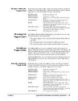
In the following example, the multimeter will accept 5 triggers from the
external trigger BNC connector. Four measurements are taken per trigger
(sample count is set to 4) and the trigger delay is 2 seconds.
dimension array
Dimension computer array.
CONF:VOLT:DC
Function: DC voltag.e
TRIG:SOUR EXT
Trigger source is external BNC on multimeter front
panel.
TRIG:COUN 5
Multimeter will accept 5 external triggers (one
measurement is taken per trigger).
SAMP:COUN 4
Take 4 measurements for each trigger.
TRIG:DEL 2
Wait 2 seconds between trigger and start of first
measurement and each subsequent measurement till
sample count reached.
READ?
Place multimeter in wait-for-trigger state; make
measurements when external triggers are received;
send readings to output buffer.
timeout may occur
May require INIT, monitor the status byte for
completion (standard event bit 0), FETC? to transfer
readings to the output buffer (vs. READ?).
enter statement
Enter readings into computer.
Summary of Contents for Agilent E1412A
Page 2: ......
Page 10: ...8 Contents Notes...
Page 14: ...12 Notes...
Page 15: ...13 Notes...
Page 16: ...14 Notes...
Page 26: ...24 Agilent E1412A Multimeter Module Setup Chapter 1 Notes...
Page 194: ...192 Agilent E1412A Multimeter Error Messages Appendix B Notes...
Page 201: ...Index 199 Index Agilent E1412A User s Manual and SCPI Programming Guide...

