Agilent E1412A Multimeter Application Information
57
Synchronizing the
Multimeter With a
Switch Module
This program example demonstrates how to synchronize the multimeter
with a switch module. For the E1412A it uses the TTL triggers from the VXI
backplane to trigger the multimeter and advance the channel scan list. The
example uses the E1476A 64-Channel Multiplexer Module but will also
work with any switch module as long as the channel list is specified
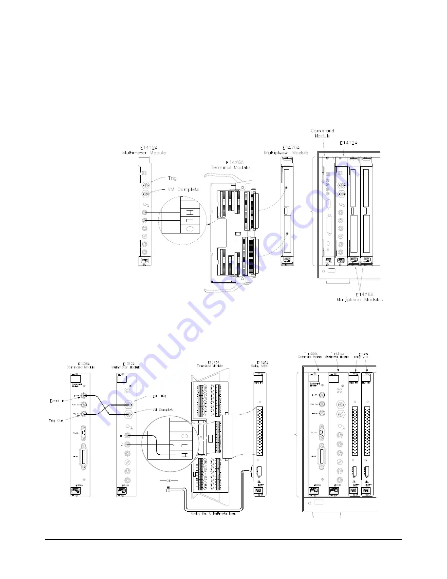
properly. Figure 2-2 illustrates the C-size set up. The switch module
(multiplexer) and multimeter use the VXI backplane to communicate the
trigger and VM Complete signals to each other to synchronize the scan.
Figure 2-3 shows the E1312A set up using external triggering. (Note: the
E1312A is obsolete and no longer supported. Figure 2-3 is for information
only.) B-size command modules do not support VXIbus TTL triggers.
Figure 2-2. E1412A Multimeter and Switch Module Synchronization
Figure 2-3. E1312A Multimeter (obsolete and unsupported) and Switch Module Synchronization
Summary of Contents for Agilent E1412A
Page 2: ......
Page 10: ...8 Contents Notes...
Page 14: ...12 Notes...
Page 15: ...13 Notes...
Page 16: ...14 Notes...
Page 26: ...24 Agilent E1412A Multimeter Module Setup Chapter 1 Notes...
Page 194: ...192 Agilent E1412A Multimeter Error Messages Appendix B Notes...
Page 201: ...Index 199 Index Agilent E1412A User s Manual and SCPI Programming Guide...

