background image

Installing the Software

2

Agilent E6474A User’s Guide

21


Registration process

The following procedure outlines the procedure for 
registering your SUS license. The benefits and features of 
registration are provided at the end of this section (refer to 

“Benefits of SUS registration"

on page 24).

1

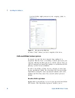
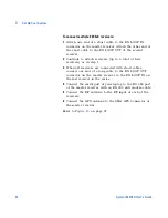
Go to http://www.agilent.com/comms/softwaremanager 
(refer to 

Figure 4

)

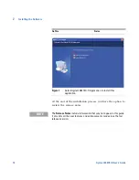
Figure 4

Initial start-up screen

2

Select  the  “Click  here  to  begin”  link.

3

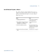
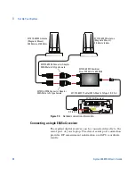
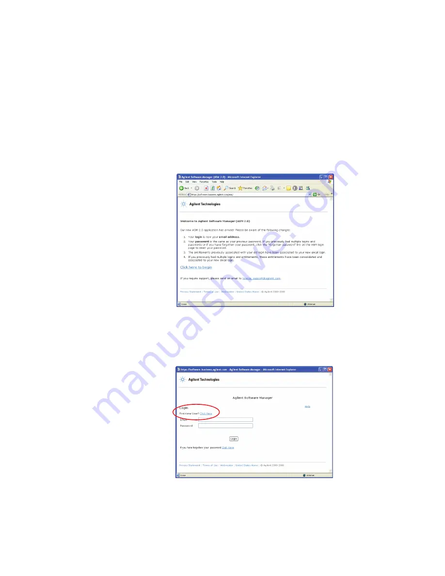
Select the “First time user? Click here” link. This takes 
you to the first stage of the registration process (refer to 

Figure 5

).

Figure 5

Login - first time user

Summary of Contents for Agilent E6474A

Page 1: ...Agilent Technologies Agilent E6474A Wireless Network Optimization Platform User s Guide ...

Page 2: ...ract or subcon tract Software is delivered and licensed as Commercial computer software as defined in DFAR 252 227 7014 June 1995 or as a commercial item as defined in FAR 2 101 a or as Restricted computer soft ware as defined in FAR 52 227 19 June 1987 or any equivalent agency regulation or contract clause Use duplication or disclo sure of Software is subject to Agilent Tech nologies standard com...

Page 3: ...s and configuration as well as in depth information about how to use the E6474A software The software also contains over two hours of video training material that helps you get the most from the application See this chapter For this information 1 Get Ready A list of tasks to perform before you get started 2 Install the Software Instructions for installing the E6474A software 3 Set Up Your System S...

Page 4: ...4 Agilent E6474A User s Guide ...

Page 5: ...orter software 17 Verifying your software installation 19 Support Software Update Service SUS Registration Procedure 20 Registration process 21 Add an additional contact person 24 3 Set Up Your System 27 Phones 28 Overview 28 Phone connection using a USB port 28 Phone connection using direct serial RS 232 port 28 Agilent Digital Receivers 29 Overview 29 Connecting a single W1314A receiver 30 Conne...

Page 6: ...iver external GPS 39 Indoor positioning 43 Batteries 44 Checking the remaining charge 44 Charging the battery 45 Safe handling and disposal 45 Indoor Setup 47 Overview 47 Setting up the timing module 47 How to switch batteries during calibration 51 Cable connections for indoor hardware 51 Cable routing through the shoulder straps 54 How to reset the 1PP2S output on the timing module 56 License Man...

Page 7: ...quencer 81 Views 84 Mapping 89 How to add and configure an indoor map 98 Collecting Data 101 Events 104 Sharing Projects and Data 111 5 Get Results Fast 119 Using the Online Training 120 To open a training topic 120 Online Help 121 Accessing Online Help 121 To search the help 121 Documentation Library 122 6 Getting Assistance If You Need It 123 Troubleshooting your E6474A system 124 Device communi...

Page 8: ...Warranty repair 132 Preparing the system for shipping 133 A Safety and Regulatory Information 135 Warning and caution notices 135 General safety considerations 135 Installation Use and Storage 136 Signal and input power 137 Symbols 137 Declaration of Conformity Agilent E64xx RF Receivers 139 Declaration of Conformity Agilent W1314A Receivers 140 B Connection Panels and LED Indicators 141 Agilent W...

Page 9: ...pan CDMA cellular band receiver specifications 160 E6453C GSM1800 and Korean CDMA band receiver specifications 162 E6454C 1 9 GHz CDMA GSM1900 receiver specifications 164 E6455C 2 1 GHz W CDMA UMTS cdma2000 receiver specifications 166 E6456C 1 9 GHz W CDMA UMTS cdma2000 receiver specifications 168 E6458C GSM 850 receiver specifications 170 E6458C 100 GSM UMTS 850 and PCS 1900 receiver specificatio...

Page 10: ...stallation 181 In Vehicle Installation Guidelines 181 Recommended Tools 183 Installation Overview 183 Installing the Mounting Plate 184 Attaching the Receiver to the Mounting Plate 185 Installing the PDM in the Vehicle 186 Mounting the E645x receiver 189 Antenna Installation 190 Installation guidelines 190 1 Index 191 ...

Page 11: ...e Agilent E6474A system is a modular system so your delivery may arrive as a collection of boxes Carefully unpack each box and locate the following items License key s Installation CD License documents Order details order number packing list NOTE Do not connect any hardware at this stage ...

Page 12: ...ware and Software Requirements on page 148 Agilent E6474A installation CD A valid license key1 Fully charged phone batteries Refer to Phones on page 28 If you are unclear about any items you have received please contact us as soon as possible Refer to Phone support Contacting Customer Support on page 131 1 If you have purchased the software licensing option then you must have access to your compan...

Page 13: ... E6474A software on page 15 Install Analysis Reporter Install Analysis Reporter software on page 17 Verify your installation Verifying your software installation on page 19 Support Software Update Service SUS Registration Procedure Support Software Update Service SUS Registration Procedure on page 20 NOTE Do not connect any hardware at this stage Refer to Set Up Your System on page 27 for more inf...

Page 14: ... main Agilent E6474A software the following items are added to your PC The E6474A application software Folders containing hardware drivers Default projects and views All documentation including help and training files NOTE It is recommended that you read the Release Notes before you install the software The Release Notes include information that may not appear in this guide It also lists all the n...

Page 15: ...cation can integrate with many external devices which provide large amounts of data therefore efficient disk access is important for optimal performance CAUTION Vista OS It is recommended that you switch off the User Account Control option to enable all the features of the E6474A application Do This Notes 1 Insert the Agilent E6474A CD This CD contains the required software device drivers 2 Your s...

Page 16: ...ou have the option to review the release notes Figure 1 Select Agilent E6474A X Application to install this application Do This Notes NOTE The Release Notes include information that may not appear in this guide It also lists all the new features and enhancements made since the last released version ...

Page 17: ... This Notes 1 Insert the Agilent E6474A CD This CD contains the required software device drivers 2 Your system may have autostart or go to the Start button click Run and type D setup where D is your CD drive The installation dialog box appears 3 Follow the installation instructions If you have a previous version installed on your PC your will be prompted to over write it with the newer version 4 S...

Page 18: ...18 Agilent E6474A User s Guide 2 Installing the Software Figure 2 Select Analysis Reporter to install this application Do This Notes ...

Page 19: ...license dongle to your PC or obtain a valid license from your license server if applicable This also applies to parallel license dongles Your PC should automatically detect the USB license dongle Refer to License Manager on page 58 2 Select Start All Programs Agilent Wireless Solutions E6474A X E6474A X The E6474A software starts Refer to License Manager on page 58 3 Select Help About E6474A X The...

Page 20: ... 1 year 3 years or 5 years An entitlement certificate This may not have been issued if the SUS license was provided as a demo or trial license prior to September 2007 The certificate provides instructions and how to register One year standard SUS 060 One year corporate SUS for greater than 50 systems 061 One year Tech Tool SUS 062 3 Years Drive Test SUS Support and Software Update Service 063 3 Ye...

Page 21: ...stration are provided at the end of this section refer to Benefits of SUS registration on page 24 1 Go to http www agilent com comms softwaremanager refer to Figure 4 Figure 4 Initial start up screen 2 Select the Click here to begin link 3 Select the First time user Click here link This takes you to the first stage of the registration process refer to Figure 5 Figure 5 Login first time user ...

Page 22: ...mail address and password refer to Figure 6 and select next Figure 6 Registration part 1 of 3 5 Enter your order number and certificate number These numbers can be found at the top of the SUS license document refer to Figure 7 and select next Figure 7 Registration part 2 of 3 ...

Page 23: ...ensure you get the best support from Agilent it is important that we have accurate and up to date contact details for your company Once you have registered you are taken to the Agilent Software Manager home page Follow this procedure to complete your contact details 1 Select the Manage my profile link refer to Figure 9 Figure 9 Manage my profile link 2 Enter your contact details Please complete as...

Page 24: ...erson in your company Having another person to contact means that you will not missing any important updates or information if the primary contact is not available To add a secondary contact in your company to the same license agreement follow the procedure used for first time registration using the same agreement number and order number but this time enter the second contact person s details Bene...

Page 25: ...our contact profile including password changes You have access to the latest software downloads and updates Tracking of SUS licences and orders Quicker and easier access to the support team which leads to quicker resolution of any outstanding issues or questions you may have ...

Page 26: ...26 Agilent E6474A User s Guide 2 Installing the Software ...

Page 27: ...to connect receivers Agilent Digital Receivers on page 29 Information about batteries Batteries on page 44 How to set up and configure an indoor system Indoor Setup on page 47 How to use the License Manager software License Manager on page 58 NOTE Do not connect hardware until you have installed the Agilent E6474A software Refer to Install the E6474A software on page 15 ...

Page 28: ...USB interface cables The USB drivers used by these phones may require custom installation processes Follow the phone manufacturer s instructions for configuring USB phone connections It is recommended that you read the phone manufacturer s instruction before you connect any devices to your laptop Phone connection using direct serial RS 232 port Depending on the type of phone you wish to connect to...

Page 29: ...an be connected and configured using the following methods Receiver configuration Refer to Connecting a single W1314A receiver page 30 Connecting multiple W1314A receivers page 30 Using the power distribution module PDM W1314A page 32 Using the Diplexer antenna connector W1314A page 33 Connecting a single E645xC receiver page 34 Connecting multiple E645xC receivers page 35 Pulse trigger the E645xC...

Page 30: ...1314A receivers A standard configuration for daisy chained receivers includes the following cables Refer to Figure 12 on page 31 RF IN W1314A 120 Quad Band Receiver 9 34VDC 18W TYP 48W MAX GPS ANT GPS 1PPS TEMP STAT 450 496 921 962 MHz 1800 1885 2100 2180 MHz 10 dBm 10 mW MAX 20 VDC MAX GPS antenna Master USB to computer BNC connector for 1 pulse per second optional Power cable Cable retainer Type...

Page 31: ... 20 VDC MAX RF IN W1314A 120 Quad Band Receiver 9 34VDC 18W TYP 48W MAX GPS ANT GPS 1PPS TEMP STAT 450 496 921 962 MHz 1800 1885 2100 2180 MHz 10 dBm 10 mW MAX 20 VDC MAX RF IN W1314A 120 Quad Band Receiver 9 34VDC 18W TYP 48W MAX GPS ANT GPS 1PPS TEMP STAT 450 496 921 962 MHz 1800 1885 2100 2180 MHz 10 dBm 10 mW MAX 20 VDC MAX BATTERY GPS Antenna Master USB to computer USB to next receiver in dai...

Page 32: ...led will sound a warning when the ignition switch is turned off The sound warning will repeat every minute and after approximately 20 minutes the power will be stopped to the attached receivers This gives you time to close the drive test software and power off equipment If ignition sense is in the off position the PDM will operate independently of the vehicle ignition One fuse per receiver to prot...

Page 33: ...rovide coverage for all available bands These receivers are supplied with two antennas and a combiner In situations where multiple bands need to be scanned you will need to use the combiner to provide adequate RF signal strength Connect the receiver to the combiner unit using the SMA M to N Type M cable Then connect the two antennas to the combiner unit using the SMA M to N Type F connector adapte...

Page 34: ...te results RF IN W1314A 120 Quad Band Receiver 9 34VDC 18W TYP 48W MAX GPS ANT GPS 1PPS TEMP STAT 450 496 921 962 MHz 1800 1885 2100 2180 MHz 10 dBm 10 mW MAX 20 VDC MAX W1314A Receiver W1314 80027 Cable SMA Male to N Type 2ft 0 7m W1314 80025 Combiner 2 way 350 MHz to 600 MHz W1314 80026 Connector Adapter SMA Male to N Type Female W1314 80026 Connector Adapter SMA Male to N Type Female W1314 8002...

Page 35: ... multiple E645xC receivers When you configure multiple receivers only one receiver the master receiver is physically connected to the computer and is able to supply input from the GPS You attach an external GPS system unless it has internal GPS to the master receiver only The other receiver s receive their GPS signal from the master receiver If other receivers contain internal GPS systems their GP...

Page 36: ...f four receivers as in step 1 3 When all receivers are connected with short cables connect one end of a long cable to the RX LOOP OUT connector on the master receiver to the RX LOOP IN on the last receiver in the series 4 Connect the serial port of your laptop to the RS 232 port of the master receiver with an RS 232 null modem cable 5 Connect the RF antenna to the RF input of each of the receivers...

Page 37: ...45xC receivers The E645xC receivers accommodate a pulse trigger device The triggering device requirements are Cable with BNC male connector the Agilent pulse trigger cable input is female BNC Falling edge trigger TTL threshold 15 volt maximum pulse level 100 nanosecond minimum pulse width of period 300 microsecond minimum pulse ...

Page 38: ...e RX LOOP IN and RX LOOP OUT ports as shown in Figure 17 Or if you have one receiver connect the pulse trigger cable to the RX LOOP IN and RX LOOP OUT ports of the same receiver Connect the cable from the pulse trigger device to the BNC connector of the pulse trigger cable For software configuration and calibration instructions refer to the online help Search for wheel pulse unit setup to locate t...

Page 39: ...gilent digital receivers are supplied with an internal GPS system When an Agilent digital receiver is connected to your system this GPS device is automatically detected GPS signals are passed to your system through the serial or USB connection Agilent digital receiver external GPS The following examples show a complete system with various external GPS systems attached through an Agilent E645xC dig...

Page 40: ...igure 18 Internal GPS with optional differential GPS Example 2 Using Placer GPS 455 In this example the external GPS unit is connected using an adapter box The adapter box is connected to the GPS RS 232 port on the receiver Refer to Figure 19 on page 41 The adapter box is connected to the MDT RTCM and Digital IO ports ...

Page 41: ...he RS 232 null modem cable included with the system Connect the remaining port of the Trimble supplied communications cable to the MDT RTCM port of the Trimble Placer GPS 455 unit 2 Connect the digital port of the adapter box to the Digital IO port of the Trimble Placer GPS 455 unit using the RS 232 cable 3 Connect the MDT RTCM port of the adapter box to the MDT port of the Trimble supplied commun...

Page 42: ...stem 4 Connect the GPS antenna to the GPS ANT port of the Trimble Placer GPS 455 unit Agilent Technologies recommends that a bulkhead mount GPS antenna be used whenever possible for improved performance Figure 20 Placer 455 GPS with differential GPS ...

Page 43: ...data for indoor environments requires the following items Detailed floor and building plan BMP or JPG format Pen tablet laptop preferred 1 PP2S signal for receiver measurement synchronization For full details on how to perform indoor measurements and configure the indoor positioning and tracking refer to Indoor Setup on page 47 and the online help ...

Page 44: ...y battery status can be seen from the LEDs on the top of the booster module LEDs Lit Capacity Remaining 4 76 to 100 3 55 to 75 2 26 to 50 1 10 to 25 1 Blinking Less than 10 PUSH 100 75 50 25 Li ION Battery test button LEDs NOTE When there is no battery status indication from the LEDs then the battery discharge may be critical You should charge the battery as soon as possible Refer to the documenta...

Page 45: ...y 2 Plug the battery charger s AC power cord into a 100 240V AC 50 60Hz power source 3 Allow approximately five hours to fully charge the battery Safe handling and disposal For the safe use of lithium ion batteries always follow the instructions provided below Improper handling of lithium ion batteries may result in injury or damage from electrolyte leakage heating ignition or explosion Batteries ...

Page 46: ...ative terminals with a metal material Do not store or carry the battery where it could come into contact with metal objects such as a key chain or necklace Never allow the battery to get wet or be immersed in water Do not place the battery in a microwave oven or high pressure container Stop charging if the battery is not charged after the prescribed charge time If leakage of the electrolyte occurs...

Page 47: ...asurements Setting up the timing module Before the timing module can be used the 1PP2S output needs to be calibrated against GPS timing signals This can take between 4 and 8 hours depending on GPS signal strength Follow this procedure to calibrate your timing module 1 Install the GPSMon1 software on any compatible laptop or PC Refer to the manufacturer s installation instructions 2 Connect the tim...

Page 48: ...4 Connect a fully charge battery with the booster module fitted to the timing module A fully charge battery lasts approximately 16 hours 5 Start the GPSMon software Refer to Figure 23 on page 49 PUSH 100 75 50 25 Li ION ANT 1 PPS RS 232 10 MHz GPSMon software Timing Module Fully charge battery GPS antenna At least four satellites optional mains AC ...

Page 49: ...strong GPS signals over the whole training process This is known as the warm up period 8 Ensure the antenna and any other equipment is adequately protected from adverse weather conditions 9 When the calibration process is completed the timing module will indicate a locked status Refer to Figure 24 on page 50 Number of satellites obtained Timing module status Timing module lock status 1 The battery...

Page 50: ...f use for collecting valid indoor data would also be four hours Similarly if the module is trained for 8 hours then you can collect data for 8 hours At least four satellites Timing module status CAUTION Do not remove power from the timing module during calibration and while configuring your hardware Doing so will lose GPS satellite lock and the calibration process will have to be re started If the...

Page 51: ... a fully charge unit 5 Remove the AC adaptor power supply Cable connections for indoor hardware Once the timing module has been calibrated you can connect the hardware for indoor measurement Refer to How to add and configure an indoor map on page 98 for more information on configuring the E6474A software Refer to Figure 25 on page 52 for cable connection information This diagram does not show the ...

Page 52: ...necting phones or other test devices Refer Figure 26 on page 53 for a recommended layout for the hardware inside the backpack RF IN W1314A 120 Quad Band Receiver 9 34VDC 18W TYP 48W MAX GPS ANT GPS 1PPS TEMP STAT 450 496 921 962 MHz 1800 1885 2100 2180 MHz 10 dBm 10 mW MAX 20 VDC MAX u ANT 1 PPS CONTROL 10 MHz P U S H 1 0 0 7 5 5 0 2 5 L i I O N PUSH 100 75 50 25 Li ION To RF Antenna USB connectio...

Page 53: ...gilent E6474A User s Guide 53 Figure 26 Backpack hardware layout RF Antenna USB connection to your laptop Battery for W1314A Receiver Timing Battery for Timing Module 1PP2S connection Agilent W1314A Receiver Backpack Module ...

Page 54: ...straps Refer to Figure 27 for a cable routing example 1 Route the USB cable E6473 60005 through either shoulder strap 2 If the phones are be attached to the shoulder straps route the phone interface cables through either shoulder strap Figure 27 Routing cables through the shoulder straps ...

Page 55: ...t belt should always remain on your hips even after the harness is adjusted 3 Tighten up the shoulder straps until the pack feels comfortable The weight of the pack should be carried on your hips for maximum comfort The shoulder straps help stabilize the pack on your body 4 Connect the chest strap You can change the vertical position so that the strap fits comfortably across your chest The sternum...

Page 56: ... software to communicate with the timing module Refer to the timing module manufacturer s instruction for installing and configuring the GPSMon software 1 Connect the timing module to your laptop 2 Provide power to the timing module using a battery or AC mains 3 From the GPSMon software select Setup Ref Pulse Control Refer to Figure 29 Figure 29 Open the Ref Pulse dialog box 4 In the Ref Pulse Con...

Page 57: ...Set Up Your System 3 Agilent E6474A User s Guide 57 Figure 30 Setting the 1PP2S option 5 Select OK The timing should now be set to 1PP2S Set 1PP2S option ...

Page 58: ...s using a check out process Typically only one server application is required per customer License Manager software is automatically installed when you install the E6474A software This software allows you to Transfer licenses between keys included for example between the DB25 parallel key and USB key Add software options to your license key Transfer licenses between keys Check out software license...

Page 59: ... instructions on using the License Manager please refer to the Welcome topic in the License Manager software s online help 1 To start the License Manager select Programs Agilent Wireless Solutions E6474A X Utilities License Manager 2 Click Help Help topics to open the online help topics ...

Page 60: ...60 Agilent E6474A User s Guide 3 Set Up Your System ...

Page 61: ... you ll find in this chapter This chapter tells you how to start configuring and using your system To do this See this Turning the power on Turning the power on on page 62 Starting the software Starting the software on page 63 Using the software Using the software on page 64 ...

Page 62: ... are fully charged before beginning data collection Refer to Batteries on page 44 for more information For an in vehicle system verify that the phone and car batteries are fully charged before beginning data collection CAUTION Before switching on any system component ensure that the supply voltages are in the specified ranges Refer to Computer Hardware and Software Requirements on page 148 ...

Page 63: ...4A X E6474A X Refer to Figure 31 Figure 31 Starting E6474A software 2 When the software starts a copyright screen is briefly displayed This is followed by the welcome screen Refer to Figure 31 on page 63 Confirm your license options Once the software has started check your license options To check your license options 1 With the application open select Help About E6474A 2 Select the License Info b...

Page 64: ...verview In Project Mode default mode drives are grouped together as collections of data files under a common named hardware configuration When you click on a project you can see a list of all the related drives collected with it Refer to the online help for more information about this mode File Mode Overview In File Mode however each drive is treated as a discrete file which can be named at collec...

Page 65: ...n open the application in project mode and create a project A project contains all your configuration information and drive test results A project is created using the project manager Once you have selected the project manager the project mode is automatically enabled Select this button to view an animated demonstration of the application Choose a project type and select this button to open and vi...

Page 66: ...e 33 Project manager 2 In the project manager window select the New Project icon Figure 34 Figure 34 New project icon 3 Optional Select a template project A template project contains pre defined views and layout 4 Enter a name for your project Figure 35 Figure 35 Project name Select Project Manager Select New Project Enter a project name ...

Page 67: ...anager to access the active project Figure 36 Default user interface project mode For more information on the project manager and how to use it refer to the online help Creating a new file Before you add hardware and configure your test environment you can open the application in file mode A file contains all your configuration information and drive test results in a single file Once you have sele...

Page 68: ...file 1 Select File New Figure 37 Figure 37 File mode 2 The user interface will open with the default layout Figure 38 Figure 38 Default user interface file mode For more information on file mode and how to use it refer to the online help Select New Default User Interface ...

Page 69: ...ace Figure 39 Default user interface Description of user interface Here is more information about the areas listed in Figure 39 on page 69 Main menus The main menus give you access to the most common tasks you may need to perform They also let you start other tools such as the export wizard and the cellsite importer Main menus Control icons Online help Device and view property panel Test sequencer...

Page 70: ... chart colors measurement limits and more Sequencer status and log views These two system views report the status of any test sequence The sequencer status view displays the progress of the test sequence while the sequencer log view displays the test results as they are reported by the system Data item and sequencer panels The data items system panel displays all the measurements that are availabl...

Page 71: ... or you need to configure projects remotely from your test area Adding hardware Manually no devices connected to your laptop Follow this procedure 1 In the hardware panel right click on hardware Figure 40 Figure 40 Hardware panel NOTE Hardware does NOT need to be connected to your system for it to be added to the hardware list This lets you configure a project without the need for you to have all ...

Page 72: ...gure 41 Add device option 3 Expand the list of available devices and select the device you want to add to your project Figure 42 Figure 42 Expanded list of devices 4 The device is added to your hardware list and is shown as not connected The data items available from the Select Add Device Select device ...

Page 73: ...nd data item lists Adding hardware Automatically with devices connected to your laptop The device add wizard is used to add hardware automatically to your laptop This wizard steps you through the connection process Then at the end of the process devices are detected and connected Device added to Data items added hardware panel ...

Page 74: ...ur System Follow this procedure 1 In the hardware panel right click on hardware Figure 44 Figure 44 Hardware panel 2 Select Device Wizard from the pop up menu Figure 45 Figure 45 Device add wizard option Right click here Select Device Wizard ...

Page 75: ...l your devices are detected Figure 46 Figure 46 Device add wizard dialogs 4 Once the application has scanned and detected your devices they are added to the hardware list and the device is shown as connected Also data items available from the device are shown below in the data items system panel Figure 47 on page 76 ...

Page 76: ... measurements Unlike a typical phone device the Agilent digital receiver is capable of providing different sets of measurements To access these measurement sets you need to add a receiver measurement after you have added the receiver hardware Device added to hardware Data items added panel and shown as connected ...

Page 77: ...de 77 To add a receiver measurement after you have added a receiver to the hardware list follow this procedure 1 Right click on the receiver hardware 2 Select Add Measurement Figure 48 Figure 48 Add a receiver measurement Select Add Measurement ...

Page 78: ...Your System 3 Choose the measurement you wish to add to the receiver Figure 49 Figure 49 Select a measurement to add 4 Select the added measurement to configure the measurement properties Figure 50 Properties that need Select a measurement ...

Page 79: ...th new items that can be used on views A receiver does not need to be connected to your system for measurements to be added Tour of Data Items Once hardware has been added to your project manually or automatically data items are added to the data items system panel Data items are used to build views Properties of the measurement Added measurement NOTE All data items and measurements are shown Howe...

Page 80: ...ms system panel Data items can be dragged and dropped onto views Refer to Views on page 84 for more information on views and view configuration Multiple data items can be selected and dragged onto views Figure 52 Figure 52 Drag and drop data items Expand the data items list to see the available measurements Drag and drop data items onto views ...

Page 81: ...e of test scenarios from a simple voice call test to full data network testing including internet connection FTP SMS and video testing dependant on you having valid licenses for these tests To create a test sequence Follow this procedure 1 Once you have added hardware right click on the service model in the sequencer system panel 2 Select New Device YourDeviceName Figure 53 Figure 53 Add a device ...

Page 82: ...e device and select New Test Select the test you wish to add Figure 54 Figure 54 Add a test Repeat step 3 to build up your test sequence Repeat step 2 to add more tests for other devices Tests can be cut copied deleted or moved in the sequencer tree Select a test to add ...

Page 83: ...eated your test sequence you can configure individual tests using the properties panel Figure 55 on the right side of the user interface Select each test to display the properties for that test Figure 55 Sequencer and properties Sequencer test Properties of the test ...

Page 84: ...t of two devices Views A view is a highly flexible user interface component that is used for displaying data items available from configured devices As with projects views can be created even if devices are not physically connected to your laptop The E6474A is supplied with a comprehensive set of custom and blank views These views have been designed to be used when performing the most common tasks...

Page 85: ...fferent devices Device Bound Views A device bound view is a view that contains particular data items from a particular device The data items on this type of custom view are bound to this view When you record data in capture mode only data from the selected device will be reported in the custom view Data items not supported by your configured device will not be displayed on the view To build a simp...

Page 86: ...in the opened view Figure 58 Figure 58 Data items list 4 Drag and drop the selected data item onto the view Figure 59 Expand list of data items NOTE You can select more than one data item at a time and drag and drop all those items onto a view Some data items because of their data format can not be displayed on some views ...

Page 87: ...ur System 4 Agilent E6474A User s Guide 87 Figure 59 Drag and drop data items onto a view Select the view to display the view properties Figure 60 Figure 60 View properties Drag and drop data items onto view ...

Page 88: ...nfigure the data item on the view Figure 61 Figure 61 Properties of data item dragged onto the view For example the type of properties you can configure are colors fonts scaling ranges color limits and more The properties for data items change depending on what type of view you have placed them on ...

Page 89: ...ations based on a file generated using the cellsite importer Refer to Adding a cellsite database to a map on page 92 for more information To add a map The mapping feature supports most vector and raster map formats Follow this procedure 1 Select View Common Views Map View Figure 62 Figure 62 Common view menu NOTE You must have a valid mapping license to use the mapping features Agilent E6474A opti...

Page 90: ...em 2 Open a map view Figure 63 Figure 63 Default map view 3 Select the map load button to open the map loading dialog box Figure 64 Figure 64 Map load button 4 Locate and add the map files you wish to load Click here to open the map load dialog box ...

Page 91: ... how to manage your maps can be found in the online help To add data items to your map Once you have added your map s you will need to select measurements to plot on the map as you drive test your network Click here to open the layer properties dialog NOTE You may experience performance issues if you try to plot too many data items on the map As a general guideline four measurement results with of...

Page 92: ...ialog box automatically displays the added data items Figure 66 Figure 66 Map layer properties with data items added 5 Select each data item to configure the appearance offset and data themed ranges Adding a cellsite database to a map Before you can add a cellsite database to a map you must get your data into the right format The correct format XML file is produced using the cellsite importer NOTE...

Page 93: ...ce file is an ASCII TAB delimited file containing raw information about the cellsites It contains information about latitude longitude cell name and sector widths and more Once a cross reference file is created it can be used to transform many source data files into the required XML output format How to use the cellsite importer Follow these steps 1 Select Tools Cellsite Importer The cellsite impo...

Page 94: ... and no blank lines and select open Figure 69 Figure 69 Example cellsite file 4 Choose which technology is to be used for the master data column headings Figure 70 Figure 70 Cellsite template master 5 Select a heading from the master data column NOTE The latitude and longitude format should be Deg Min Sec OR signed decimal format ...

Page 95: ... the source data viewer for verify the data format Figure 71 Figure 71 Source data viewer 7 optional You can select which data format to use for the master and source match For example height can be in feet meters or none default This can be selected using the Available Format s dialog area Example of source data ...

Page 96: ... Use Your System 8 Select Add The matched pair of data items are added to the Match Template Figure 72 Figure 72 Master and Source matched data items Select master item Select source item Choose a data format if applicable Select add ...

Page 97: ...ta items 10 Select Create Matched Data to save the output of the cellsite importer Refer to the online help for more information on using the cellsite importer How to add a valid cellsite to a map To add a cellsite select Tools Options and select the Cell Site tab Locate and select the correct cellsite file and enable the link to map option Figure 74 ...

Page 98: ...map The E6474A software supports indoor or in building measurements These are measurements that have been taken without the direct reference to GPS satellite signals When testing technologies that require accurate timing references it is recommended that you use a calibrated timing source Refer to Indoor Setup on page 47 for more information How to load and configure an indoor map 1 Open a map vie...

Page 99: ... indoor icons 4 In the map load dialog box enter a Locate and select a indoor floor plan BMP or JPG b Enter the floor plan outer dimensions Meters or Feet c Select a map corner as a reference point from the drop down list dialog d Enter the corresponding map reference coordinates for the selected reference point Refer to Figure 77 on page 100 Select Indoor Mapping Mode Two icons added to menu ...

Page 100: ...a How to collect indoor measurements 1 Zoom into the area where you are starting you indoor data collection 2 Select the Anchor icon and click on the floor plan you current location 3 Select the Log or Live mode buttons and wait a few seconds for hardware to start reporting measurement data 4 Start walking to your next way point 5 Click on the map at you next way point 6 Repeat this process until ...

Page 101: ...you quickly collect data once you have set up your project and test environment To collect data Follow this procedure 1 Create or open a project 2 Add and configure your hardware 3 Create a test sequence 4 Create and arrange your views NOTE Views are not required to collect data All data items are logged and can be reviewed after data collection is completed ...

Page 102: ...all device connections are checked and then measurement data will be collected and added to the current project When you wish to stop data collection select the stop button The drive test data is displayed as a drive data set within the project Figure 80 Figure 80 Drive data in project Select Log Mode button Drive data in project ...

Page 103: ... data collection or playback you can double click on a line chart map event or protocol message and the user interface will synchronize all open views to the data point in time where you clicked Data continues to be logged and recorded even though you may have jumped back in time Play Pause Stop Step Backward Step Forward Playback speed Live Mode Log Mode Playback progress Relative Absolute time b...

Page 104: ...event data sources These triggers can then initiate a series of actions play a sound display a text message or display a marker Event action display can be controlled during data logging so you can focus on particular system issues as they develop Once an event has been added to your project or file it is automatically added to a range of views These views are Line Chart Map Protocol Spectrograph ...

Page 105: ...w these steps 1 Configure a project with one or more devices 2 Start the Add Event Wizard refer to Figure 82 Figure 82 Starting the Add Event Wizard 3 Select the Create Event button Figure 83 Figure 83 Create a new event button 4 Enter the name description of the event 5 Select the event data source ...

Page 106: ...Set the conditions for triggering the event Figure 84 Figure 84 Typical event conditions 7 Set the actions to be performed when the event is triggered Figure 85 Figure 85 Select each action to configure 8 Select Finish when you have completed the process ...

Page 107: ...e triggering conditions If more than one device in your project can provide the triggering conditions then you will be given an additional stage where you have to assign the right devices to the right event condition sources Figure 86 Figure 86 Select device and action to assign 4 Confirm that the conditions and actions are what you want for your event 5 Select Finish to copy the event to your pro...

Page 108: ...View System Panels Active Event List 2 Select the Expand icon to show all the events in the project Figure 87 Figure 87 List of active events in your current project Sharing Import Export you events with other users You can import and export events that you have created by other users Events are exported and imported to and from simple XML format files similar to the format and process used for ma...

Page 109: ...3 Select the move over button 4 You are asked to provide a name for the file that will contain the exported events If you wish to append the events to an existing file first open that file using the New file icon button 5 Select OK to complete the export process Follow these steps to import someone else s events 1 Select Configuration Events Library 2 Select the Open file icon button and locate th...

Page 110: ...file 4 Select the move over button 5 Select OK to close the Events Library and complete the import process To view events while data logging use the Events Output View system panel Select View System Panels Event Output View NOTE If you already have an event with the same name and you are exporting or importing events you will be asked to rename the event to prevent any conflicts ...

Page 111: ...tion with other engineers To share a drive file that was collected using file mode simply transfer the single drive file AOD to the person you wish to share the information with To export a project with data The project manager is used for exporting projects and associated data Follow this procedure 1 Open the project manager 2 Select the project to be exported Figure 90 Figure 90 Select project S...

Page 112: ...e 92 Select data to export 5 Either choose a folder to export to or create a new folder 6 The export progress dialog box opens and displays the export results Figure 93 Figure 93 Export progress dialog box If you wish to share the project and data with others the whole folder and the exported content needs to be transferred Select Export Project button Select drive data to be export with your proj...

Page 113: ...utlines the process To import a project with data The project manager is used for importing projects and associated data Follow this procedure 1 Open the project manager 2 Select the import project button Figure 94 Figure 94 Import project button 3 Locate and select the project folder to be imported Figure 95 Figure 95 Import project folder dialog box Select Import Project button ...

Page 114: ...nd drive test data now appears in the project manager To import an SD5 file An SD5 file format is a drive test data file from previous versions of the E6474A software 9 4 and before To import an SD5 file follow this procedure 1 Open the project manager 2 Select the import SD5 button Figure 97 Figure 97 Import SD5 file 3 Locate and select the SD5 file to be imported Select import SD5 button ...

Page 115: ...ve data is created and added to the project list in the project manager It is now possible to configure and playback the drive test data using default views or your own views To export your views If you have created a particular view or set of views that you think will be of use to your engineers in the field then these views can be shared using the manage views dialog box Any import issues are li...

Page 116: ...00 Internal views list 3 Select the move across button to place the views in the External File area The Save View File Dialog box opens 4 Enter a name of the file into which you are going to save your views Select Manage Views NOTE Only the views you have created modified or imported to your current project are available for export The standard system supplied views can not be exported Open extern...

Page 117: ...External File area 2 Locate and open the external file The custom views contained in the external file are displayed in the external file area 3 Select the views from the Internal Views list that you wish to add to the external file 4 Select the move across button to add the views to the list 5 Select OK and close the manage views dialog box How to import custom views If you have a file containing...

Page 118: ... System 5 Optional If the name of an imported custom view is the same as a view you already have in your project the rename dialog box is displayed Rename the imported custom view and select OK 6 Select OK and close the manage views dialog box ...

Page 119: ...Using the Online Training on page 120 Get information about taking measurements Online Help on page 121 WARNING Vehicle drivers should not operate the Agilent E6474A system while the vehicle is in motion NOTE It is It is recommended that you look at the online training videos before configuring and collecting data Using the Online Training on page 120 ...

Page 120: ...you through those tasks in a simulation of the program To open a training topic Do this See this 1 Click Start All Programs Agilent Wireless Solutions E6474A X This starts the Agilent E6474A application 2 Expand the online help contents 3 Select the Training Demonstrations link in the online help contents Refer to Figure 101 for details Figure 101 Training topics link 4 Scroll through the list of ...

Page 121: ...click the Help button when shown to display the help topic with detailed information about the options check boxes and text boxes 2 For help on configuring a view open the view then press F1 The online help displays topics in a separate window from the application This window has a print icon if you wish to print a particular topic To search the help 1 Select the Search help button 2 Enter the tex...

Page 122: ...it can be applied to range of technologies To access the library 1 Start the E6474A Application 2 Select Help Library This opens a web page that contains links to PDF Adobe Portable Document Format files These files include User s Guides reference documents technical overviews and other related documents NOTE To view the PDF files you need to have the Adobe reader application installed on your PC ...

Page 123: ... your system Troubleshooting your E6474A system on page 124 Online frequently asked questions Online Frequently Asked Questions on page 127 Update E645xx receiver firmware Updating Receiver Firmware on page 128 Contact Customer Support Short these pins to update the firmware on page 130 Return the system for service Returning the System for Service on page 132 ...

Page 124: ...o device connected to it A phone is communicating at the wrong baud rate The device itself is defective Remedies Before using the Probe Device command to probe the COM port to identify the devices verify that all devices are connected and powered on Devices include phones receivers and navigators Refer to Chapter 3 for cable connection details If you have an iDEN phone perform the procedure under ...

Page 125: ...t arrow key until Set Baud Rate value is displayed 6 Press the key under OK in the display 7 Press the right arrow key until 19200 is displayed 8 Press the key under OK in the display 9 Press the key under Exit in the display Toshiba phone power up issues Toshiba direct connect phone power up Toshiba JCDMA phones have special power up procedures Each time you power up the system you must perform t...

Page 126: ... Press the key 5 Press the following keys F 9 6 The F key is to the right of the toggle button 6 Press the F key 7 Choose the DIAGE option 8 Press the F key 9 Power the computer on Toshiba 301T 1 Unplug the interface cable from the phone 2 Plug the phone interface cable into the phone The phone will power up 3 Press the following keys F 9 0 The F key is to the right of the toggle button 4 Press th...

Page 127: ...ance refer to the web site at http www agilent com find E6474A To access the frequently asked questions section 1 Click on the Technical Support tab 2 Click on the FAQ tab 3 Navigate up or down the FAQ links to find the appropriate FAQ topic If you do not have access to the web contact your local Agilent Technologies representative for information ...

Page 128: ...TE The Agilent W1314A receiver range uses a software enabled firmware upgrade process that is managed by the E6474A software If the firmware or internal components require updating follow the instructions provided when you try to connect your receiver to the software application NOTE If your hardware configuration includes daisy chained E645xx receivers you must first disconnect the receivers then...

Page 129: ...t the firmware programming dongle into the Rx Loop Out port of the receiver as shown in Figure 105 Figure 105 Receiver with dongle attached 4 Click OK When the update is complete the dialog box shown in Figure 106 appears This indicates that the update is complete Figure 106 Firmware update successful dialog box 5 Remove the dongle from the receiver Stop and restart data logging ...

Page 130: ...e key you can order a new one order from your Agilent Technologies representative E6450 60007 or you can substitute a piece of wire that shorts pins 8 to 10 on the RX LOOP OUT connector see Figure 107 Remember to follow on screen instructions and remove the wire when you are prompted by the software Figure 107 Short these pins to update the firmware ...

Page 131: ...he amount of free hard disk space Your E6474A Wireless Network Optimization Platform software includes 12 months of Response Center Support To use the telephone assistance 1 Install the software 2 The Customer Business Center will provide you with a packet of information which includes your system handle number Please refer to that number when you call for support To establish a Support Contact pl...

Page 132: ...pair after examining the unit When a system is returned to Agilent Technologies for servicing it must be adequately packaged see Preparing the system for shipping on page 133 and have a complete description of the failure symptoms attached When describing the failure please be as specific as possible about the nature of the problem Include copies of additional failure information such as receiver ...

Page 133: ...vered when you first received the system 3 Pack the system in the original shipping containers Original materials are available through Agilent Technologies office See step 4 for more information 4 Wrap the system in anti static plastic to reduce the possibility of damage caused by electrostatic discharge For systems weighing less then 54 kg 120 lbs use a double walled corrugated cardboard carton ...

Page 134: ...er electrical connectors to protect sensitive components from electrostatic damage Instrument damage can result from using packaging materials other than the original materials Never use styrene pellets as packaging material They do not adequately cushion the system or prevent it from shifting in the carton They may also cause system damage by generating static electricity Do This Additional Infor...

Page 135: ...ion and warnings which must be followed by the user to ensure safe operation and to maintain the product in a safe condition WARNING The WARNING notice denotes a hazard It calls attention to a procedure practice or the like that if not correctly performed or adhered to could result in personal injury Do not proceed beyond a WARNING notice until the indicated conditions are fully understood and met...

Page 136: ...ove the covers To prevent electrical shock disconnect the equipment from mains before cleaning Use a dry cloth or one slightly dampened with water to clean the external case parts Do not attempt to clean the receiver internally CAUTION The Agilent 645xC and W1314A digital receivers are designed for use in INSTALLATION CATEGORY II and POLLUTION DEGREE 2 per IEC 61010 1 and 664 respectively Enclosur...

Page 137: ... type of rating type nA nV The use of other fuses or materials is prohibited If you use external power install the instrument so the detachable power cord is readily identifiable and is easily reached by the operator The detachable power cord is the instrument disconnecting device It disconnects the mains circuit from the mains supply before other parts of the instrument If you do not use external...

Page 138: ...e instrument is an Industrial Scientific and Medical Group Class A product CISPER 11 Clause 4 The C Tick mark is a registered trademark of the Spectrum Management Agency of Australia This signifies compliance with the Australian EMC Framework Regulations under the terms of the Radio Communications Act of 1992 ICES 001 This ISM device complies with Canadian ICES 001 Cet appareil ISM est conforme a ...

Page 139: ...A1 1998 A2 2001 EMC Standard CISPR 11 1990 EN 55011 1991 IEC 61000 4 2 1995 A1998 EN 61000 4 2 1995 IEC 61000 4 3 1995 EN 61000 4 3 1995 IEC 61000 4 4 1995 EN 61000 4 4 1995 IEC 61000 4 5 1995 EN 61000 4 5 1996 IEC 61000 4 6 1996 EN 61000 4 6 1998 IEC 61000 4 11 1994 EN 61000 4 11 1998 Limit Group 1 Class A 4 kV CD 8 kV AD 3 V m 80 1000 MHz 0 5 kV sig 1 kV power 0 5 kV L L 1 kV L G 3 V 0 15 80 MHz...

Page 140: ...mended by 93 68 EEC and conforms with the following product standards Standard Limit EMC IEC 61326 2002 EN 61326 2006 CISPR 11 EN 55011 IEC 61000 4 2 EN 61000 4 2 IEC 61000 4 3 EN 61000 4 3 IEC 61000 4 4 EN 61000 4 4 IEC 61000 4 5 EN 61000 4 5 IEC 61000 4 6 EN 61000 4 6 IEC 61000 4 8 EN 61000 4 8 IEC 61000 4 11 EN 61000 4 11 Canada ICES 001 2004 Australia New Zealand AS NZS CISPR 11 2004 Group 1 C...

Page 141: ...nectors and LED indicators on the Agilent W1314A and E645xC receivers along with the Trimble Placer 455DR For this information See this W1314A receiver Agilent W1314A Receivers on page 142 E645xC receiver E645xC Receiver on page 143 Trimble Placer GPS 455DR Trimble Placer GPS 455DR on page 144 Fei Zypher Timing Module Fei Zypher Timing Module on page 145 ...

Page 142: ...or multiple receivers Connecting multiple W1314A receivers on page 30 GPS 1PPS GPS timing port Connect a pulse source GPS 1PPS to provide a timing pulse for measurement synchronization when a GPS signal is not available GPS Ant GPS antenna connector Connect to GPS antenna Temp Temperature LED Displays a warning when the receiver temperature is over limit Refer to the online help for more informati...

Page 143: ...ith GPS option GPS RS 232 External GPS data port For CDMA receivers an optional 1 PPS cable may be connected to this port if the external navigator provides a 1 pulse per second signal For E6455A E6456A and E645xC receivers the cable for a wheel pulse trigger may be connected to this port Rx Loop In Receive data loop input Connect to Rx Loop Out of second receiver if equipped Rx Loop Out Receive d...

Page 144: ...e computer this option requires a Dual Serial Port PCMCIA card MDT RTCM If you have a Differential GPS connect its data cable to this port This port is also used for sensor calibration When calibrating remove the cable from the Radio port then connect it to the MDT RTCM port When calibration is complete reconnect the cable to the Radio port Heading Sensor Trimble p n 30513 Heading Sensor lead Conn...

Page 145: ...L 10 MHz Connector Name Cable Part Number Opposite End of Cable Connects To ANT GPS antenna 1PPS Connects to the 1PPS port on the W1314A receiver and provides timing and measurement synchronization RS 232 Used for controlling the timing module Not used by the Agilent E6474A system 10 MHz Provides a 10 MHz signal output Note used by the Agilent E6474A system Power Input not shown above Agilent batt...

Page 146: ...146 Agilent E6474A User s Guide B Connection Panels and LED Indicators ...

Page 147: ...ded computer specifications Computer Hardware and Software Requirements on page 148 Battery specifications Battery Specifications W1314A 070 on page 149 Receiver specifications Receiver Specifications on page 151 W1314A antenna specifications W1314AAntennaSpecifications on page 176 List of supported phones Phone Support on page 177 ...

Page 148: ...ing XP for Pen tablet Intel Core Duo T2500 2GHz 2GB RAM Parallel port or USB Port for software key PCMCIA slot or a USB connection for multiple hardware support 50GB hard disk space CD ROM drive recommended for installation 1280 x 1024 display resolution minimum Recommended minimum Windows Vista requirements Vista Business Intel Core Duo T2500 2GHz 3GB RAM Parallel port or USB Port for software ke...

Page 149: ... 8V 7 2 Ah Storage Temperature Range Storage Temperature Limits 20 C to 60 C The battery packs should be stored in an environment with low humidity free from corrosive gas at a recommended temperature range 21 C Extended exposure to temperatures above 45 C could degrade battery performance and life Weight 1 11 lbs 0 506 kg NOTE The battery is defined as a consumable part and is only covered by a 9...

Page 150: ...provides a convenient alternative to placing spent nickel metal hydride battery packs into the trash or municipal waste stream which is illegal in some areas For information on recycling the battery outside the US please check with your local Agilent sales office Power cable The battery pack charger is equipped with a three wire power cable in accordance with international safety standards When co...

Page 151: ... temperature Characteristics Provide useful information by giving non warranted performance parameters Characteristics information describes product information for parameters that are either not subject to variation non measurable verifiable through functional pass fail tests or as a matter of routine not measured Characteristics are printed in italics Calibration Cycle Agilent Technologies warra...

Page 152: ...20V DC characteristic 1 dB compression point 15 dBm typical Adjacent channel rejection Internally generated spurious input referred 55 dB nominal 120 dBm Input Output RF input 50Ω nominal Type N VSWR 2 0 typical Connectors Computer USB 2 0 High Speed GPS SMA Female Power DC power jack 100 mils positive center USB 4 port hub USB 2 0 Miscellaneous Operating temperature range 0 C to 55 C Maximum rela...

Page 153: ...Specifications C Agilent E6474A User s Guide 153 GPS Integrated internal GPS 12 Channel Type Item Description Specification ...

Page 154: ... to 55 C Accuracy 30 kHz IF 0 5 typical 25 dBm to 100dBm 1 5 dB from 40 dBm to 100 dBm 20 to 30 C 2 5 dB from 40 dBm to 100 dBm 0 to 55 C Accuracy 200 kHz IF Noise figure 8 0 dB typical Maximum safe input level 10 dBm 20V DC characteristic 1 dB compression point 15 dBm characteristic Adjacent channel desensitization Adjacent channel rejection Internally generated spurious input referred 25 dBm typ...

Page 155: ...type SMA Differential compatible without dead reckoning Note Internal GPS is standard on all C receivers It can be disabled if you wish to use an external GPS system It is recommended the input signal level not exceed 40 dBm Adjacent channel desensitization applies to wideband mode 1 25 MHz IF filter and is defined as 1 dB compression of tuned signal with interfering signal 1 25 MHz from tuned sig...

Page 156: ... dB typical Maximum safe input level 10 dBm 20V DC characteristic 1 dB compression point 15 dBm characteristic Adjacent channel desensitization Adjacent channel rejection Internally generated spurious input referred 25 dBm typical 45 dB typical 120 dBm Input Output RF input 50Ω Type N Connectors Computer RS 232 DB9 Male GPS RS 232 DB9 Male Power DC power jack 100 mils positive center Miscellaneous...

Page 157: ...out dead reckoning It is recommended the input signal level not exceed 25 dBm Adjacent channel desensitization applies to the wideband mode 1 25 MHz IF Filter and is defined as 1 dB compression of tuned signal with interfering signal 1 25 MHz from tuned signal Adjacent channel rejection applies to the narrowband mode 200 kHz IF filter and is defined as Suppression of interfering signal 200 kHz fro...

Page 158: ...ccuracy 200 kHz IF 0 5 typical 1 5 dB from 40 dBm to 100 dBm 20 to 30 C 2 5 dB from 40 dBm to 100 dBm 0 to 55 C Noise figure 8 0 dB typical Maximum safe input level 10 dBm 20V DC characteristic 1 dB compression point 15 dBm characteristic Adjacent channel desensitization Adjacent channel rejection Internally generated spurious input referred 25 dBm typical 45 dB typical 120 dBm Input Output RF inp...

Page 159: ...thout dead reckoning Note Internal GPS is standard on all C receivers It can be disabled if you wish to use an external GPS system It is recommended the input signal level not exceed 40 dBm Adjacent channel desensitization 1 dB compression of tuned signal with interfering signal 1 25 MHz from tuned signal Adjacent channel rejection applies to the narrowband mode 30 kHz IF filter and is defined as ...

Page 160: ...ccuracy 30 kHz IF 1 5 dB from 40 dBm to 100 dBm 20 to 30 C 2 5 dB from 40 dBm to 100 dBm 0 to 55 C Noise figure 8 0 dB typical Maximum safe input level 10 dBm 20V DC characteristic 1 dB compression point 15 dBm characteristic Adjacent channel desensitization Adjacent channel rejection Internally generated spurious input referred 25 dBm typical 45 dB typical 120 dBm Input Output RF input 50Ω Type N...

Page 161: ...g Note Internal GPS is standard on all C receivers It can be disabled if you wish to use an external GPS system It is recommended the input signal level not exceed 40 dBm Adjacent channel desensitization 1 dB compression of tuned signal with interfering signal 1 25 MHz from tuned signal Adjacent channel rejection applies to the narrowband mode 30 kHz IF filter and is defined as Suppression of inte...

Page 162: ... 5 typical 25 dBm to 100 dBm Noise figure 8 dB typical Maximum safe input level 10 dBm 20V DC characteristic 1 dB compression point 15 dBm characteristic Adjacent channel desensitization Adjacent channel rejection Internally generated spurious input referred 25 dBm typical 45 dB typical 120 dBm Input Output RF input 50Ω Type N Connectors Computer RS 232 DB9 Male GPS RS 232 DB9 Male Power DC power ...

Page 163: ...hout dead reckoning Note Internal GPS is standard on all C receivers It can be disabled if you wish to use an external GPS system It is recommended the input signal level not exceed 25 dBm Adjacent channel desensitization applies to the wideband mode 1 25 MHz IF Filter and is defined as 1 dB compression of tuned signal with interfering signal 1 25 MHz from tuned signal Receivers with the exception...

Page 164: ...Bm to 100 dBm Noise figure 8 dB typical Maximum safe input level 10 dBm 20V DC characteristic 1 dB compression point 15 dBm characteristic Adjacent channel desensitization Adjacent channel rejection Internally generated spurious input referred 25 dBm typical 45 dB typical 120 dBm Input Output RF input 50Ω Type N Connectors Computer RS 232 DB9 Male GPS RS 232 DB9 Male Power DC power jack 100 mils p...

Page 165: ...eckoning Note Internal GPS is standard on all C receivers It can be disabled if you wish to use an external GPS system It is recommended the input signal level not exceed 25 dBm Adjacent channel desensitization applies to the wideband mode 1 25 MHz IF Filter and is defined as 1 dB compression of tuned signal with interfering signal 1 25 MHz from tuned signal Receivers with the exception of C recei...

Page 166: ... dBm 20 to 30 C Noise figure 8 0 dB typical Maximum safe input level 10 dBm 20V DC characteristic 1 dB compression point 15 dBm characteristic Adjacent channel desensitization Adjacent channel rejection Internally generated spurious input referred 20 dBm typical 25 dB typical 120 dBm for 1 25 MHz 115 dBm for 5 MHz Input Output RF input 50Ω Type N Connectors Computer RS 232 DB9 Male GPS RS 232 DB9 ...

Page 167: ...dead reckoning Note The internal GPS can be disabled if you wish to connect an external GPS system It is recommended the input signal level not exceed 40 dBm Adjacent channel desensitization applies to wideband mode 5 MHz IF filter and is defined as 1 dB compression of tuned signal with interfering signal 5 MHz from tuned signal Adjacent channel rejection applies to the narrowband mode 1 25 MHz IF...

Page 168: ... figure 8 0 dB typical Maximum safe input level 10 dBm 20V DC characteristic 1 dB compression point 15 dBm characteristic Adjacent channel desensitization Adjacent channel rejection Internally generated spurious input referred 20 dBm typical 25 dB typical 120 dBm for 1 25 MHz 115 dBm for 5 MHz Input Output RF input 50Ω Type N Connectors Computer RS 232 DB9 Male GPS RS 232 DB9 Male Power DC power j...

Page 169: ...ng Note The internal GPS can be disabled if you wish to connect an external GPS system 1It is recommended the input signal level not exceed 40 dBm Adjacent channel desensitization applies to wideband mode 5 MHz IF filter and is defined as 1 dB compression of tuned signal with interfering signal 5 MHz from tuned signal Adjacent channel rejection applies to the narrowband mode 1 25 MHz IF filter and...

Page 170: ...00 kHz IF 0 5 typical 1 5 dB from 40 dBm to 100 dBm 20 to 30 C 2 5 dB from 40 dBm to 100 dBm 0 to 55 C Noise figure 8 0 dB typical Maximum safe input level 10 dBm 20V DC characteristic 1 dB compression point 15 dBm characteristic Adjacent channel desensitization Adjacent channel rejection Internally generated spurious input referred 25 dBm typical 45 dB typical 120 dBm Input Output RF input 50Ω Ty...

Page 171: ...hout dead reckoning Note Internal GPS is standard on all C receivers It can be disabled if you wish to use an external GPS system It is recommended the input signal level not exceed 40 dBm Adjacent channel desensitization 1 dB compression of tuned signal with interfering signal 1 25 MHz from tuned signal Adjacent channel rejection applies to the narrowband mode 200 kHz IF filter and is defined as ...

Page 172: ...474A technology measurements Item Description Specification Frequency Frequency range downlink 869 to 894MHz and 1930 to 1990MHz Frequency accuracy With GPS time synchronization 1 ppm 0 05 ppm characteristic IF bandwidth 1 25 MHz characteristic 200 kHz characteristic Aging of TCXO 1 ppm year Amplitude Accuracy 1 25 MHz IF 0 5 typical 1 dB from 40 dBm to 100 dBm 20 to 30 C 2 dB from 40 dBm to 100 d...

Page 173: ... 9 to 34 V DC 9W 9 to 34 V DC 10W Transformer AC Power supplied with receiver 100 240 Volts AC 50 60 Hz Internal GPS Option 200 GPS Receiver 8 Channel internal GPS receiver Connector type SMA Differential compatible without dead reckoning Note Internal GPS is standard on all C receivers It can be disabled if you wish to use an external GPS system It is recommended the input signal level not exceed...

Page 174: ...om 40 dBm to 100 dBm 0 to 55 C Noise figure 8 0 dB typical 1 dB compression point 15 dBm characteristic Adjacent channel desensitization Adjacent channel rejection Internally generated spurious input referred 25 dBm typical 45 dB typical 120 dBm Input Output RF input 50Ω Type N Connectors Computer RS 232 DB9 Male GPS RS 232 DB9 Male Power DC power jack 100 mils positive center Miscellaneous Intern...

Page 175: ...d on all C receivers It can be disabled if you wish to use an external GPS system It is recommended the input signal level not exceed 40 dBm Adjacent channel desensitization 1 dB compression of tuned signal with interfering signal 1 25 MHz from tuned signal Adjacent channel rejection applies to the narrowband mode 30 kHz IF filter and is defined as Suppression of interfering signal 30 kHz from tun...

Page 176: ...4A RF Receiver combiner kit Figure 112 W1314A Multi Band Antenna W1314 80023 Multi Band Antenna Frequency Gain 700 1250MHz 3 dBi peak 1650 2000MHz 5dBi peak 2100 2700MHz 3dBi peak 1700 2700MHz 0dBi without groundplane VSWR 2 1 W1314 80024 Multi Band Antenna Frequency Gain 2 3 GHz to 6 0 GHz 3 dBi across band VSWR 2 1 Black Radome W1314 80023 White Radome W1314 80024 ...

Page 177: ...A list of supported phones is supplied with the Agilent E6474A software This list can be found in the library To view a list of supported phones 1 Open the Agilent E6474A application software 2 Select Help Library 3 Select the Supported phones and cables list link ...

Page 178: ...w Mach Pan HD 12 14 THD 0 75in LG 5182 1295 VELCRO STRAP 0 5 X 8 12 7mm x 203mm W1314 00001 Mounting Bracket W1314 40001 Bumper W1314 80004 Antenna GPS SMA Connector 3V W1314 80010 USB 1 1 Cable 15 Ft 5m W1314 80013 USB 1 1 Cable 6 Ft 2m W1314 80025 Antenna Combiner Module W1314 80026 Connector Adapter SMA Male to N Type Female W1314 80027 RF Cable SMA Male to N Type Male 2ft 0 7m Part Number Desc...

Page 179: ...tions E6450C PCS CDMA receiver 1 9GHz E6451C GSM receiver 900 MHz E6452C Cellular CDMA receiver 850 MHz E6457C Cellular CDMA receiver 800 MHz Japan cellular band E6453C GSM Korean band CDMA receiver 1 8GHz E6454C PCS CDMA GSM receiver 1 9GHz E6455C IMT 2000 band W CDMA UMTS CDMA receiver 2 1 GHz with GPS E6456C W CDMA UMTS cdma2000 1 9 GHz with GPS E6458C GSM850 Receiver with GPS E6458C 100 E6458C...

Page 180: ...nclude the following hardware items Component Part Number Description Software license key for Parallel port E6474 10002 Can be programmed with the E6474A software options that you have ordered using the License Manager software Plugs into the computer s Parallel port Software license key for USB port E6474 10003 Contains the E6474A software options that you have ordered Plugs into the computer s ...

Page 181: ...sing a permanently installed cellular antenna follow the antenna manufacturer s installation instructions Antennas should be spaced at least 18 45cm apart to minimize interference WARNING Before installing this product check your vehicle warranty for any special instructions regarding the installation of third party products Agilent assumes no responsibility for any vehicle warranty issues arising...

Page 182: ...nectors Be sure to allow room for the mounting plate Observe local regulations and restrictions when installing the equipment and making electrical connections to the vehicle Use caution when drilling holes and working around critical areas such as the fuel tank fuel lines battery engine compartment electrical harnesses fuse block and the exhaust system Disconnect the battery before making permane...

Page 183: ...ed components into a vehicle Details follow in subsequent sections 1 Install the W1314A mounting plate in a suitable location 2 Make connections to the W1314A receiver a Connect the GPS antenna b Connect power c Connect the 1 pulse per second cable if required d Connect the RF antenna e Make appropriate USB connections f Turn on power to the receiver and verify that the LED sequence is correct ref...

Page 184: ...flat surface of the vehicle to which the mounting plate can be securely attached 2 Mark the holes for the 12 mounting screws on the mounting surface according to the hole pattern of the plate refer to Figure 113 on page 185 3 Drill the holes using a 3 32 2 5mm drill bit or the metric equivalent that accommodates the screw 4 Attach the mounting plate to the vehicle using the hardware provided NOTE ...

Page 185: ...ate in either direction Before you attach it determine which direction best fits the available space For example if space is tight mount the receiver as shown in Figure 114 on page 186 to minimize the space used at the rear of the receiver The orientation shown in Figure 114 also provides the best protection for cables It is recommended that you connect cables before mounting the receiver if possi...

Page 186: ...ceiver 1 Pull the latch tab to release it 2 Lift the receiver up approximately one inch 25mm then slide the receiver forward and lift out Installing the PDM in the Vehicle 1 Locate a flat surface of the vehicle to which the PDM can be securely attached Refer to Figure 115 on page 187 2 Mark the holes for the 12 mounting screws on the mounting surface according to the hole pattern of the PDM Latch ...

Page 187: ...32 5 5mm drill bit or the metric equivalent that accommodates the screw 4 Attach the PDM to the vehicle using the hardware provided Figure 115 Installing the PDM Connecting Cables to the PDM A standard configuration for the PDM includes the following cables Refer to Figure 116 on page 188 82 57 mm 199 6 mm ...

Page 188: ...ttery The red cable connects to the positive terminal through a fuse block The fuse block should be located as close to the power connection point as possible The blue cable connects to the ignition run circuit to provide ignition sense to the PDM See Figure 117 on page 189 Cable retainer Power cable connects to spare battery NOTE If the ignition sense feature is not used the blue cable should be ...

Page 189: ...ounting the E645x receiver Use the following guidelines for installing the Agilent E645x receiver Locate a flat surface of the vehicle to which the base plate can be securely attached Attach the base plate to the vehicle using the hardware provided Ignition circuit Black cable Red cable Blue cable Fuse Holder 20 Amp mini type BATTERY ...

Page 190: ...as of high vibration Also avoid mounting the antenna near a roof luggage rack The rack could block the signal For permanent mount antennas choose a location with access both above and below the antenna mounting surface this is required for installing fasteners and for routing the antenna cable For permanent mount antennas use silicone sealant to prevent water leakage between the antenna base and t...

Page 191: ...t 92 click n sync 103 collect data 102 collection buttons 103 combiner antenna 33 insertion loss 33 combiner unit 33 cable W1314 80027 33 combiner unit W1314 80025 33 common test tasks 84 compliance symbols 137 Computer requirements 148 connected hardware 75 connection combiner 34 connections 141 more than one receiver 35 receiver to serial port 34 receivers 143 Trimble Placer 455 144 contacting A...

Page 192: ...t SD5 progress 115 importer cellsites 92 indoor cable connections 51 indoor hardware 47 connections 52 indoor positioning 43 Indoor setup 47 insertion loss 33 install the software 15 installation analysis reporter 17 installation safety 136 Internal GPS with external differential GPS 40 introduction hardware and software requirements 65 In vehicle system installation 181 antennas 190 ISM Mark 138 ...

Page 193: ...dd a test 82 edit 82 how to create a sequence 81 status and log views 70 system panel 81 test properties 83 service model 81 set up your system 27 Setting the iDEN phones baud rate 125 setting up timing module 47 sharing projects 112 sharing views 115 signal and power inputs 137 single receiver 30 Software Support Update Service 15 software installation Agilent E6474A 15 Verifying 19 software lice...

Page 194: ...ties 88 exporting 115 import 117 list of views 85 map 90 properties 87 Vista operating system 15 148 W W1314 80023 Multi band antenna 176 W1314 80024 antenna 176 W1314A multiple receiver connection 30 PDM Module 32 single receiver connection 30 specifications 140 WARNING batteries 46 Warning and Caution defined 135 warranty 132 battery 45 149 What is on the CD 14 Windows Vista Operating System 148...

Reviews: