182
3
English URL
www.agilent.com/find/products
16720A
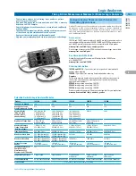
View Scope
Pattern Generator Module and View Scope Logic Analyzer/Oscilloscope Correlation
Logic Analyzers
Unleash the Complementary Power of a Logic
Analyzer and an Oscilloscope
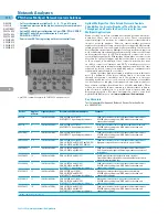
Easily make time-correlated measurements between an Agilent logic
analyzer and oscilloscope. The time-correlated logic analyzer and
oscilloscope waveforms are integrated into a single logic analyzer
waveform display for easy viewing and analysis.
Specifications
View Scope Features, Connection and Compatibility
View Scope Capabilities Include
• Automatic de-skew of the waveforms
• Trigger the oscilloscope from the logic analyzer (or vice versa)
• Precisely relate information on the instrument displays with
tracking markers
• Maintain tight time-correlation across deep memory acquisitions
with synchronized sampling clocks
Logic Analyzer/Oscilloscope Connection
• Use standard LAN connection and two BNC cables to connect
Trigger In and Trigger Out
Agilent Oscilloscope Capabilities
• Maximum Scope Bandwidth: 13 GHz
• Maximum Sampling Rate: 40 GSa/s
• Maximum Memory Depth: 128 M points
• Channels per Oscilloscope: 2 and 4
Compatible Agilent Oscilloscopes
• 80000B Infiniium Series High Performance Lab Oscilloscopes
• 8000 Infiniium Series General Purpose Lab Oscilloscopes
• 6000 Series High-performance Portable Oscilloscopes
• 5000 Series Portable Oscilloscopes
Compatible Logic Analyzers
• 16800 Series Portable Logic Analyzers
• 16900 Series Modular Logic Analyzers
• 1690 Series PC-hosted Logic Analyzers
• 1680 Series Logic Analyzers
Key Literature & Web Link
Agilent Technologies Measurement Modules for the 16900 Series Data
Sheet, p/n 5989-0422EN
Agilent Technologies 16900 Series Logic Analysis System Mainframes
Data Sheet, p/n 5989-0421EN
View Scope Logic Analyzer and Oscilloscope Correlation Data Sheet,
p/n 5989-4646EN
www.agilent.com/find/logic _modules
Digital Stimulus for Performing Functional
Verification, Debugging and Stress Testing
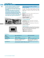
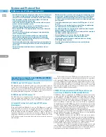
The Agilent 16720A digital pattern generator module for Agilent’s
16900 Series logic analysis systems is ideal for the functional testing
of your digital design. The pattern generator is used to simulate
infrequently encountered test conditions in hardware design and
software program testing. You can also use a pattern generator to
stimulate your electronic designs with ideal or faulty digital
patterns for performing functional verification, debugging and
stress testing.
Agilent 16720A Pattern Generator Module
Half Channels
Full Channel
Maximum Clock Speed
300 MHz
180 MHz
Memory Depth in Vectors
16 M
8 M
Maximum Number of
24
48
Channels per Timebase
Maximum Vector Width
120 bits
240 bits
Stimulus Commands
Initialize, block, repeat, and break macros
Logic Levels Supported
5 V TTL, 3-state TTL, 3-state CMOS, 3-state
3.3 V, ECL, 5 V PECL, 3.3 V LVPECL,
3-state 2.5 V, 3-state 1.8 V, LVDS
Accessories
Pod Options for 16720A Pattern Generator
Option 011
TTL clock pod & lead set
Option 013
3-state TTL/CMOS data pod & lead set
Option 014
TTL data pod & lead set
Option 015
2.5 V clock pod & lead set
Option 016
2.5 V 3-state data pod & lead set
Option 017
3.3 V clock pod & lead set
Option 018
3.3 V 3-state data pod & lead set
Option 021
ECL clock pod & lead set
Option 022
ECL (terminated) data pod & lead set
Option 023
ECL (unterminated) data pod & lead set
Option 031
5 V PECL clock pod & lead set
Option 032
5 V PECL data pod & lead set
Option 033
3.3 V LVPECL clock pod & lead set
Option 034
3.3 V LVPECL data pod & lead set
Option 041
1.8 V clock pod & lead set
Option 042
1.8 V 3-state data pod & lead set
Option 051
LVDS clock pod & lead set
Option 052
LVDS data pod & lead set
Ordering Information
When ordering the 16720A, please note the following:
You must order at least one clock pod for each 16720A module used as a
master. You must order at least one data pod for every 8 output channels.
The 10483 is the recommended replacement for the discontinued 10466A.
Summary of Contents for All
Page 1: ......

