background image

206

3

English URL 

www.agilent.com/find/products

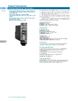
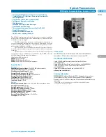
N4903A

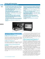
J-BERT High-Performance Serial BERT N4903A 12.5 Gb/s and 7 Gb/s

Serial Bit Error Ratio Tester

The Smartest Way to Accurate Jitter Tolerance Test and
Characterization

The J-BERT N4903A High-Performance Serial BERT provides the
only complete jitter tolerance test solution for characterization of
serial gigabit devices. 

It offers complete, integrated and calibrated jitter composition

for stressed eye testing of receivers up to 12.5 Gb/s. Automated and
compliant jitter tolerance testing allows quick and accurate charac-
terization for all popular serial bus standards, such as PCI Express,
SATA, FB-DIMM, Display Port, Fibre Channel, CEI, 10 Gigabit
Ethernet and XFP/XFI. 

The J-BERT matches the latest serial bus interfaces perfectly

with its ability to analyze undeterministic traffic with idles from the
DUT with the analyzer’s Bit Recovery Mode. The pattern generator
allows setting up complex pattern sequences to bring a device into
loop back mode. To match LVDS and other low voltage standards, all
clock, data inputs and outputs are differential and can handle small
amplitude swings. 

Clockless interfaces can be analyzed with the built-in CDR with

tunable loop bandwidth (option CTR). The J-BERT offers differen-
tial subrate clock outputs with any ratio of clock and data signals
without extra equipment. Data and clock outputs support spread
Spectrum Clocking (SSC), commonly used in computer bus 
standards. 

The J-BERT is an expandable, future-proof BERT platform

where all options can be configured to the current test needs and
upgraded later when those needs change. 

It is the ideal choice for R&D and validation teams who charac-

terize and stress chips and transceiver modules with serial I/O ports
up to 12.5 Gb/s. 

Specifications

Pattern Generator

Operation Range

Internal clock: 620 Mb/s to 12.5 Gb/s (option C13 and G13) or 
7 Gb/s (option C07 and G07)
External clock: 150 Mb/s to 12.5 Gb/s (option C13 and G13) or 
7 Gb/s (option C07 and G07)

Data Output

1, differential or single-ended

Output Amplitude

0.1 Vpp – 1.8 Vpp

Jitter

<9 ps pp

Transition Time

<25 ps (10% to 90% and ECL levels)

Crossing Point Adjustable

20% – 80%

Pattern

PRBS 2

n

–1, n = 7, 10, 11, 15, 23, 31

User-definable memory: 32 Mbit and pattern sequencing

Delay Control Input

200 ps @ 1 GHz

Jitter Tolerance Test

Jitter Sources, Built-in & Calibrated

(option J10)

Random Jitter:

0 to 14 ps rms, up to 1 GHz

Periodic Jitter:

sinewave, rectangular modulation up to 20 MHz, 

sinusoidal modulation up to 300 MHz

Sinusoidal Jitter:

multiple UIs up to 5 MHz

Bounded Uncorrelated Jitter:

up to 200 ps pp; according CEI

SSC Clocking

(option J11)

triangular modulation – 0.5% @ 28 to 34 kHz on data and clock outputs

Interference Channel

(option J20)

ISI:

Intersymbol interference by switchable board traces 

Sinusoidal Interference

: vertical eye closure, common and differential

mode 

Error Detector:

Operation Range

Internal clock: 500 Mb/s to 12.5 Gb/ s (option C13) or 7 Gb/s (option C07)
External clock: 150 Mb/s to 12.5 Gb s (option C13) or 7 Gb/s (option C07)

Data Input

1, differential or single-ended

Delay Adjust

±0.75 ns 

Clock Data Recovery

Fixed loop bandwidth: data rate/1667
Variable loop bandwidth (option CTR): 100 kHz to 12 MHz

Sensitivity

<50 mV

Measurement Suite

BER, accumulated, intervals
BERT Scan, “bathtub” curve includes RJ, DJ, TJ
Output Level 
Eye Diagram with BER contour and eye masks
Fast Eye Mask
Spectral Jitter
Error Location Capture
Fast Total Jitter Measurement

• Operating range 150 Mb/s to 7 Gb/s or to 12.5 Gb/s provides

enough margin for today’s and tomorrow’s serial interfaces 

• Built-in, compliant and calibrated jitter injection with >0.5 UI 

(option J10). All in one box: PJ, SJ, RJ, BUJ for stressed eye 
testing of a receiver

• Interference channel plug-in with ISI and sinusoidal interference

for emulating channel and noise effects (option J20)

• Automated jitter tolerance test saves programming time 

(option J10) 

• Transition times <20 ps and jitter <9 ps pp for accurate 

measurements 

• Built-in Clock Data Recovery (CDR). Tunable loop bandwidth and

compliant CDR settings (option CTR)

• Differential pattern and clock generation and differential analysis
• Sub-rate clock outputs with any ratio 1:n 
• Bit recovery mode to analyze undeterministic traffic (option A01)
• External Delay Control Input for injection of external jitter 
• SSC clocking (option J11)
• Fast Total Jitter and measurement suite 
• Remote programmable via GPIB, LAN, and USB interfaces.

Compatible with existing command set Agilent 71612, 81630
series, N4900 series 

• Bench use with intuitive touch-screen user interface based on

Windows XP

• Applications: PCI Express

®

, SATA, Fully-buffered DIMM, Display

Port, Fibre Channel, CEI, 10 Gb Ethernet, XFP/XFI 

Summary of Contents for All

Page 1: ......

Page 2: ...alyzers 149 Logic Analyzers 179 System and Protocol Test 191 Bit Error Ratio Testers 203 Optical Transmission 212 Digital Multimeters 216 Power Meters 233 Electronic Counters 243 LCR Resistance Meters 250 Component Test Instruments 259 Signal Source Analyzer 268 Dynamic Signal Analyzer 270 OSCILLOSCOPES ANALYZERS METERS 3 ...

Page 3: ...nd logic analysis features MegaZoom technology for fast and deep memory all the time Agilent Offers a Wide Range of Oscilloscopes Model Bandwidth Sample Rate Analog Channels Digital Channels Memory Depth Handheld 20 40 MHz 200 MSa s 2 125 Kpts U1600A Series Economy 60 200 MHz 500 M 1 GSa s 2 4 Kpts DSO3000 Series Portable 100 500 MHz 2 4 GSa s 2 or 4 1 Mpts standard DSO5000 Series High Performance...

Page 4: ...00A Series comes with a standard USB 2 0 full speed inter face This together with the bundled PC Link application software enables remote control and data transfer to PC With the PC Link application software you can also perform storing retrieval and documentation of your data Multi language Quick Help Support The built in Quick Help menu is designed to give you instant assis tance and is availabl...

Page 5: ...ectangular Hamming Hanning Blackman Harris Amplitude Display Selectable in amplitude display of 1 dB 2 dB 5 dB 10 dB Digital Multimeter Specifications2 of reading of range DC Voltage Up to 600 V AC Voltage Up to 600 V AC DC Voltage Up to 600 V Resistance Up to 60 MΩ Capacitance Up to 300 µF Diode Up to 1 V Measurement Characteristics Full Scale Reading 6000 count DC Voltage True RMS AC Voltage Max...

Page 6: ...h a pre defined mask clearly highlighting signal changes Large 15 cm 5 9 in color display Up to 1 GSa s sample rate and 4 k points of memory Advanced triggering including edge pulse width and line selectable video 20 automatic measurements and 4 math functions with FFTs USB connectivity and Scope Connect software standard GPIB and RS232 connectivity available Mask test standard Sequence Mode Frame...

Page 7: ...be 10070C 1 1 20 MHz passive probe N2774A 50 MHz current probe ac dc N2775A Power supply for N2774A 10076A 100 1 4 kV 250 MHz high voltage probe N2771A 1000 1 15 kV 50 MHz high voltage probe Optional Accessories N2861A Communications Module Provides GPIB and RS 232 connectivity and pass fail output for automatic testing Warranty Options All models include a standard 1 year warranty Contact your lo...

Page 8: ... than a traditional DSO can provide Easily See Complex Interactions with an MSO Mixed signal oscilloscopes MSOs with 2 or 4 scope channels plus 16 logic channels combine the detailed signal analysis of a scope with the multi channel timing measurements of a logic analyzer Full width Pattern Triggering Flexible triggering capabilities across all scope and logic channels so you can easily isolate an...

Page 9: ...ish URL www agilent com find products 3 Specifications DSO5012A DSO5014A DSO5032A DSO5034A DSO5052A DSO5054A Bandwidth 100 MHz 100 MHz 300 MHz 300 MHz 500 MHz 500 MHz Sample Rate 2 GSa s 2 GSa s 2 GSa s 2 GSa s 2 GSa s 2 GSa s each channel each channel each channel each channel each channel each channel 4 GSa s max 4 GSa s max Channels 2 4 2 4 2 4 Display Color 1024 x 768 6 3 XGA LCD with 265 inte...

Page 10: ... Battery option 1 1 1 There is either an upgrade or for pay option available advanced serial triggering and decode available on 4 or 4 16 channel models only English URL www agilent com find products Features General Purpose High Performance DSO5000 DSO6000 MSO6000 Channel Channel count 2 or 4 analog Sample Rate Maximum sample rate 4 GSa s Display XGA display 256 intensity levels update rate 100 0...

Page 11: ...g you to correlate high speed digital control signals with slower analog signals capture infrequent events and then quickly zoom in on the details to narrow in on problems Unlike deep memory options on alternative scopes Agilent MegaZoom is not a special mode with sluggish response It s always on always fast and always there to help you capture the most critical signals with maximized sample rates...

Page 12: ...annels MSOs combine all of the measurement capabilities of a digital storage oscilloscope DSO with some of the measurement capabilities of a logic analyzer along with serial protocol analysis in a single instrument With an MSO you are able to see multiple time aligned analog parallel digital and serially decoded waveforms on the same display MSOs allow you to trigger on any combination of analog a...

Page 13: ...tion of MegaZoom enhances the responsiveness of this deep memory technology while maintain ing its mode free operation MegaZoom III provides The most responsive deep memory available The highest definition color display available Fastest update rate uncompromised Available Applications and Options The 6000 Series oscilloscopes are not only a powerful portable oscil loscope standard in their off th...

Page 14: ...ect 500 ps peak detect 250 ps peak detect 250 ps peak detect Triggering Source Internal selection of CH1 CH2 CH3 CH4 Line and Ext Modes Edge Pattern Pulse Width TV Sequence Duration Nth edge and Serial Protocols of I2 C SPI USB CAN LIN advanced CAN LIN and FlexRay available through add on optional applications Display Type High Definition color LCD Resolution XGA 1024 horizontal x 768 vertical 256...

Page 15: ...e Probe Requires 1142A power supply N2916B Rackmount Kit for 5000 6000 Series Scope N2917B Transit Case for 5000 6000 Series Scope 1180CZ Testmobile Scope Cart N2919A Testmobile Bracket for 1180CZ and 6000 Series Scope N2918A Oscilloscope Evaluation Kit for 6000 Series Scope Application Options Digital Analysis N5406A FPGA Dynamic Probing Xilinx N5434A FPGA Dynamic Probing Altera Serial Data Analy...

Page 16: ...I class C compliant and is 100 com patible with 6000A Series Oscilloscope it enables an easy transition from development to manufacturing Engineers can use the LXI class C compliant 6000A Series portable oscilloscope during the R D phase using the display keypad and knobs When your product moves to manufacturing you can use a system optimized 6000L Series LXI oscilloscope without a display Specifi...

Page 17: ...cope channel Agilent IO Libraries Suite 14 2 1 year warranty GPIB extender LAN crossover cable rack mount hardware Standard Probes Included Passive Probes Logic Cable Kit Comes with MSO Upgrade Kit DSO6014L 10074C 10 1 passive probe 54826 68701 MSO logic qty 4 cable kit qty 1 DSO6034L 10073C 10 1 passive probe 54826 68701 MSO logic qty 4 cable kit qty 1 DSO6104L 10073C 10 1 passive probe 54826 687...

Page 18: ...icult to access test points Open Windows XP Pro Interface Infiniium s intuitive Windows based graphical user interface GUI coupled with its analog like control knobs puts the scopes powerful measurements waveform math functions advanced analysis capa bilities and triggering at your fingertips Infiniium s open Windows XP Professional architecture is a robust environment for installing third party o...

Page 19: ...15 ps rms 15 ps rms 11 ps rms 11 ps rms Triggering Source All Channels Scope Channels 1 4 and Logic Channels D0 D15 External Modes Edge glitch line pattern state delay by time delay by events TV violation triggers pulse width setup hold and transition Jitter 8 ps 0 05 ppm x delay setting rms Display 8 4 inch diagonal color TFT LCD Maximum waveforms second 8 800 Waveform Measurements Voltage Peak t...

Page 20: ...buses with search functions for a particular packet CAN serial data N5402A 5989 3632EN View both protocol and physical layer analysis software information directly on the Infiniium Save time with automatic decode Easily sort through data with click and zoom High speed serial N5384A 5989 0108EN Effectively validate signal integrity data analysis Recover embedded clock signals then software display ...

Page 21: ...MSO8064A and DSO8064A 1130A 1 5 GHz 1 GHz with MSO8104A and DSO8104A both1 2 1 Depending on probe head used 2 For a complete probing solution also order a connectivity kit or individual probe head s Key Literature Web Link Infiniium 8000 Series Oscilloscopes Data Sheet p n 5989 4271EN Infiniium Probes Accessories and Options Data Sheet p n 5989 7141EN Agilent Oscilloscope Probes and Accessories Se...

Page 22: ... M 0 25 0 5 M 0 25 0 5 M 0 25 0 5 M 0 25 0 5 M 0 25 0 5 M 0 25 0 5 M Max Memory 1 2 M 64 M at 4 GSa s Option 001 standard on DSA Models Rise Time Fall Time 20 80 23 ps 25 ps 30 ps 38 ps 48 ps 91 ps 108 ps 152 ps 10 90 33 ps 36 ps 42 ps 54 ps 70 ps 105 ps 108 ps 152 ps Noise 3 3 mV 2 7 mV 2 3 mV 2 1 mV 1 8 mV 1 4 mV 1 2 mV 1 0 mV rms at 100 mV div Hardware Sensitivity 5 mV div to 5 mV div to 5 mV d...

Page 23: ...z 6 GHz 8 GHz Description Hi BW Hi BW Hi BW Hi BW Differential Single Ended Differential Differential Single Ended Differential Differential Differential Differential Differential Browser Browser Solder in Socket Solder in SMA SMA Solder in Browser ZIF Solder in Diff Capacitance 0 21 pF 0 21 pF 0 33 pF 0 32 pF 0 67 pF 0 27 pF 0 34 pF 0 50 pF Infiniimax Probing Systems Connectivity Kits and Misc E2...

Page 24: ...5411A Serial ATA Compliance Wizard based framework supporting both SATA gen 1 and gen 2 N5412A SAS Compliance Wizard based framework for Serial Attached SCSI N5413A DDR2 Full Compliance Wizard based framework solution for both clock and data characterization N5416A USB 2 0 Compliance Wizard based framework based on USB IF developed MATLAB script N5431A XAUI Compliance Wizard based framework for In...

Page 25: ...rds require jitter decomposition for compliance The DCA J provides simple one button setup and execution of advanced waveform analysis Jitter Mode decomposes jitter and amplitude interference into its constituent components and presents jitter data in various insightful displays Jitter Mode operates at all data rates the DCA J supports The 86100C brings several key attributes to jitter analysis Ve...

Page 26: ... system Windows XP Pro allows external applications to be installed Eye Diagram Mask Testing The DCA J provides efficient high throughput waveform compli ance testing with a suite of standards based eye diagram masks The test process has been streamlined into a minimum number of keystrokes for testing at industry standard data rates Essential tools for the high speed digital designer Wide bandwidt...

Page 27: ...clock recovery modules are available to derive a timing reference directly from the waveform to be measured The 83496B provides the highest performance flexibility as it is capable of operation at any data rate from 50 Mb s to 13 5 Gb s on single ended and differential electrical signals single mode 1250 to 1620 nm and multimode 780 to 1330 nm optical signals with extremely low residual jitter PLL...

Page 28: ... 8 5 20 62 5 16 86106B 1 1 1000 1600 28 40 9 7 410 1 1 1000 1600 28 40 9 7 86116A 1 1 1000 1600 53 63 9 86116B 1 1 1480 1620 65 80 9 86116C1 3 1 1 1480 1620 65 80 9 3 Dual Electrical 54754A 0 2 18 86112A 0 2 20 86117A 0 2 50 86118A 0 2 70 1 Module has receptacle to supply power for external probe For modules without a probe power receptacle use the 1143A Probe Power Supply 2 Pick any 4 rates 155 M...

Page 29: ... connector Input Return Loss 30 dB 30 dB 20 dB 20 dB HMS 10 connector fully filled fiber Electrical Channel Specifications Electrical Channel Bandwidth 18 and 40 GHz 43 and 63 GHz 80 55 and 30 GHz 80 55 and 30 GHz Transition Time 10 to 90 19 5 ps 18 GHz 8 1 ps 43 GHz 6 4 ps 55 GHz 6 4 ps 55 GHz calculated from TR 0 35 BW 9 ps 40 GHz 5 6 ps 63 GHz 4 4 ps 80 GHz 4 4 ps 80 GHz RMS Noise Characteristi...

Page 30: ...Gb s 4 0 µW 1310 nm 1550 nm 2 666 Gb s 1 3 µW 2 666 Gb s to 4 25 Gb s 1 5 µW 4 25 Gb s to 11 3 Gb s 2 5 µW Scale Factor per division Minimum 20 µW 2 µW Maximum 500 µW 100 µW CW Accuracy single marker referenced to average power monitor 25 µW 2 10 GHz 25 µW 3 25 µW 4 15 GHz 25 µW 10 CW Offset Range referenced two divisions from screen bottom 1 µW to 3 µW 0 2 µW to 0 6 µW Average Power Monitor speci...

Page 31: ... 35 BW 28 2 ps 12 4 GHz 17 5 ps 20 GHz RMS Noise Characteristic 0 25 mV 12 4 GHz 0 5 mV 20 GHz Maximum 0 5 mV 12 4 GHz 1 mV 20 GHz Scale Factor Minimum 1 mV division Maximum 100 mV division DC Accuracy single marker 0 4 of full scale 2 mV 1 5 of reading channel offset 12 4 GHz 0 4 of full scale 2 mV 3 of reading channel offset 20 GHz DC Offset Range referenced to center of screen 500 mV Input Dyna...

Page 32: ...me 5 5 Electrical Input 3 5 mm male 3 5 mm male TDR Module 54754A TDR Step Rise Time Oscilloscope TDR Performance 40 ps nominal Normalized Characteristics Adjustable from larger of 10 ps or 0 08 x time division Maximum 5 x time division TDR Step Flatness Oscilloscope TDR Performance 1 after 1 ns from edge 5 less than 1 ns from edge Normalized Characteristics 0 1 Low Level 0 00 V 2 mV High Level 20...

Page 33: ...s guide two 50 Ω SMA Terminations and one SMA short 54754A Differential TDR Module with Dual 18 GHz TDR Electrical Channels N1020A 6 GHz TDR Probe Kit N1024A TDR Calibration Kit Trigger Module 86107A Precision Timebase Reference Module 86107A 010 2 5 and 10 GHz Clock Input Capability 86107A 020 10 and 20 GHz Clock Input Capability 86107A 040 10 20 and 40 GHz Clock Input Capability Clock Recovery M...

Page 34: ...lder in Probe Head and Accessories Includes 16 Full Bandwidth and 8 Medium Bandwidth Damping Resistors and 24 Zero Ohm Ground Resistors Order E2672A for Replacement Accessories InfiniiMax I Connectivity Kits popular collections of the above probe heads E2669A InfiniiMax Connectivity Kit for Differential Measurements E2668A InfiniiMax Connectivity Kit for Single ended Measurements InfiniiMax II Act...

Page 35: ...0442B 10437B 1144A3 1145A3 1141A3 10073C 10076A 10070C 1163A1 54701A4 MSO DSO6000 300 MHz 1 GHz 10073C 10076A N2771A 10070C 1156A 11306 1141A3 1146A 1147A 1144A3 1145A3 N2772A N2780 1 2 3A7 MSO DSO6000 100 MHz 10074C 10076A N2771A 10070C 1141A2 3 1146A N2772A N2780 1 2 3A7 54645A D 10074C 10440B N2771A 10070C 1171A1 1144A2 3 1145A2 3 1141A2 3 1146A 10076A N2772A N2780 1 2 3A7 54621A D 10074C 10440...

Page 36: ...17 pF 10076A 1 8 m 100 1 66 7 MΩ 3 pF 250 MHz 1 MΩ 7 to 20 pF 1 Probe ID pin 10070 Passive Divider Probe Series Other 10070 Series Probe Accessories Accessory p n Probe tip to BNC m adapter 5081 7705 Replacement parts accessory kit 5081 7690 SMT probe accessory kit 10072A 0 5 mm IC probing kit 10075A Retractable hook tip qty 2 N2769A Alligator ground lead qty 2 N2770A Other Accessories Accessory p...

Page 37: ...rcuit under test These probe sockets are designed for use with the 1160A family and 10400B family of passive probes Ordering Information N2766A Horizontal Mini Probe Socket qty 25 N2768A Vertical Mini Probe Socket qty 25 10400B Passive Divider Probe Series Model Length Division Ratio Circuit Loading Typical Scope Bandwidth Compensates Oscilloscope Input 10437B 2 m 1 1 50 Ohm 50 Ohm 10439B1 1 5 m 1...

Page 38: ...edance Passive 1 5 m 1 1 1 MOhm 50 pF scope input 25 MHz3 1 MOhm 1163A 500 Ohm Resistive Divider 1 5 m 10 1 500 Ohm 1 5 pF 1 5 GHz2 50 Ohm 1164A High Impedance Passive 2 0 m 10 1 10 MOhm 10 pF 500 MHz1 1 MOhm 6 9 pF 1165A High Impedance Passive 1 5 m 10 1 10 MOhm 10 pF 600 MHz4 1 MOhm 12 14 pF 1 System bandwidth with 54810A 15A 20A 25A 3 System bandwidth with all Infiniium scopes 2 System bandwidt...

Page 39: ...13A Wedge probe adapter 0 5 mm 3 signal qty1 E2613B Wedge probe adapter 0 5 mm 3 signal qty2 E2614A Wedge probe adapter 0 5 mm 8 signal qty1 E2615A Wedge probe adapter 0 65 mm 3 signal qty1 E2615B Wedge probe adapter 0 65 mm 3 signal qty2 E2616A Wedge probe adapter 0 65 mm 8 signal qty1 E2643A Wedge probe adapter 0 5 mm 16 signal qty1 E2644A Wedge probe adapter 0 65 mm 16 signal qty1 10467 68701 0...

Page 40: ... the IC and doesn t require expansion beforehand as a clip does it can be inserted while the board is active Plus it s mechanically noninvasive so it won t damage your device under test 10075A and 10467 68701 0 5 mm IC Clip Accessory Kit The 10075A includes four 0 5 mm IC clips 10467 68701 and two dual lead adapters for use with passive probes Plug the probe tip into one end of the adapter and con...

Page 41: ...ign electronic high power converters and numerous other situations where signals are floating above earth ground The N2772A differential probe has an input impedance of 10 MOhm and the CMRR is 50 dB at 1 MHz The probe requires a 9 V dc battery or N2773A power supply The power supply has selectable ac frequency settings for 115 V and 230 Vac at 50 Hz 60 Hz and 400 Hz Ordering Information 1141A 200 ...

Page 42: ...Active Probe The 1144A features 800 MHz bandwidth 1 MΩ input resistance 2 pF input capacitance 10 1 attenuation and 40 Vdc peak ac maximum input voltage The 1144A can access power directly from the 54520 and 54540 series and the 54615B and 54616B oscillo scopes These oscilloscopes provide power for two channels of active probing If four channels of probing are needed a special one input two output...

Page 43: ...ution for probing 0 5 mm and 0 65 mm IC packages See page 87 for more information This probe can access power directly from the 54520 40 series and 54615 16B oscilloscopes The 1142A power supply is required for all other instruments This configuration requires 50 Ohm inputs Ordering Information 1130A 1 5 GHz InfiniiMax Active Probe System 1131A 3 5 GHz Infiniimax Active Probe System 1132A 5 GHz In...

Page 44: ...all components The 54006A is supplied with 10 1 500 Ω and 20 1 1 kΩ resistive dividers 1146A Oscilloscope AC DC Current Probe This ac dc current probe expands oscilloscope applications into industrial automotive or power environments and is ideal for analysis and measurement of distorted current waveforms and har monics This probe permits accurate display and measurement of currents from 100 mA to...

Page 45: ...ballasts and amplifiers The high signal to noise ratio of the N2782A and N2783A makes them ideal for making low level current measurements in milliamphere ranges Accurate Current Measurement A built in DEMAG demagnetize function allows the removal of any residual magnetism that has built up in the magnetic core due to power on off switching or excessive input current In addition volt age offset or...

Page 46: ...How IBM Solved a Mystery Customer Success Story 5988 5655EN The Truth About the Fidelity of High Bandwidth Voltage Probes Application Note 1404 5988 6515EN The Next Generation in Automated Oscilloscope Test Application Note 5989 5989EN Evaluating Oscilloscope Sample Rates vs Sampling Fidelity Accurate Digital Measurements Application Note 5989 5732EN Improve your Ability to Capture Elusive Events ...

Page 47: ...ike conventional swept analyzers Fourier based analyzers can measure dynamic signals because they measure all frequen cies simultaneously not one at a time Fourier analyzers are especially useful on low frequency signals 100 kHz or where very fast measurements are desired Applications include acoustic modal vibration or rotating machine analysis Vector Signal Analyzers VSAs provide capabilities th...

Page 48: ...B 110 dB 108 dB 106 dB 108 dB 88 dB 96 dB 93 dB 89 dB Dynamic Range 1 GHz Displayed Average 168 dBm2 163 dBm2 151 dBm1 160 dBm2 166 dBm2 3 125 dBm1 146 dBm2 3 148 dBm2 144 dBm2 Noise at 1 GHz Standard Attenuator 70 dB 70 dB 70 dB 60 dB 75 dB 65 dB 40 dB 70 dB 51 dB Range Step 2 dB 2 dB 10 dB 10 dB 5 dB 5 dB 1 dB 1 dB 1 dB Overall Amplitude 62 dB 78 dB 1 9 dB 95 dB 1 0 dB 1 1 dB 1 5 dB 2 0 dB 1 5 d...

Page 49: ...Digital Mod Analysis 2 2 GSM EDGE 2 2 Noise Figure 2 2 Phase Noise TD SCDMA 2 2 W CDMA HSDPA HSUPA WiMAX Mobile 3 WiMAX Fixed 3 3 3 AM FM Tune and Listen 2 2 WLAN 3 3 1xEV DO 2 2 856x 859x Programming 2 2 Code Compatibility Suite Stimulus Response 89601A Link Connectivity Remote Interface RS 232 1 1 GPIB LAN 10 100 100 100 USB 2 04 2 0 2 0 1 1 1 1 1 1 Removable storage 3 5 floppy USB Memory card U...

Page 50: ...ors and 25 wireless format 128 Msa based measurement setups complex Depends on analyzers or oscilloscopes linked to 89601A PC software 2 tones at 6 dB below full scale 31 dBm at input Signal Source Analyzer Phase Noise Measurement Solutions Frequency Phase Noise Sensitivity Functions Available Model Page Range depends on offset frequency Number 10 MHz to 7 GHz 135 dBc Hz 1 kHz offset to Phase nois...

Page 51: ... dynamic range of your measurement Gated Sweep Analyze time varying signals such as pulsed RF time division multiple access TDMA interleaved and burst modulated with gated sweep capability This type of time gating makes fast spectrum measurements on burst signals without interference from switching the carrier on and off EMC Use the PSA to make conducted and radiated emissions measure ments Now av...

Page 52: ...level trigger or burst trigger to start the PSA gated sweep according to the nature of time varying signals under test External Source Control Option 215 The external source control measurement personality available on all the PSA Series models E4440A 43A 45A 46A 47A 48A enables these high performance spectrum analyzers to control Agilent PSG or ESG signal generators for scalar network analysis up...

Page 53: ... analysis GSM with EDGE Option 202 This option includes both Global System for Mobile Communications GSM and Enhanced Data Rates for GSM Evolution EDGE measurements based on the latest standards The following measurements are quick easy to make and standards based transmit power GMSK power versus time PvT GMSK phase and frequency error GMSK output RF spectrum ORFS GMSK transmitter band spurious ED...

Page 54: ...t s pioneering efforts in CDMA measurement tech niques this personality provides quick and easy measurement setups for ACPR and SpurClose with TIA EIA IS 95A J STD 008 and IS 97D 98D standards and following measurements modulation accuracy rho code domain analysis channel power adjacent channel power ratio close in spurious NADC PDC Option BAE Both the North American Digital Cellular NADC and Pers...

Page 55: ... Free run line video RF burst external front external rear Trigger delay Span 0 Hz or FFT 150 ms to 500 ms Span 10 Hz swept 1 µs to 500 ms Resolution 0 1 µs Sweep trace Point Range Span 0 Hz 2 to 8192 Span 10 Hz 101 to 8192 Gated FFT Maximum span 10 MHz Delay range 150 to 500 ms Delay resolution 100 ns or 4 digits whichever is more Gate duration 1 83 RBW 2 nominal Gated Sweep Span range Any span G...

Page 56: ...dBm 149 dBm 20 GHz to 26 5 GHz 143 dBm 145 dBm Preamp On Option E4443 45 40A 1DS 100 kHz to 200 kHz 159 dBm 162 dBm 200 kHz to 500 kHz 159 dBm 162 dBm 500 kHz to 1 MHz 163 dBm 165 dBm 1 MHz to 10 MHz 166 dBm 168 dBm 10 MHz to 500 MHz 169 dBm 170 dBm 500 MHz to 1 1 GHz 168 dBm 169 dBm 1 1 GHz to 2 1 GHz 167 dBm 168 dBm 2 1 GHz to 3 0 GHz 165 dBm 166 dBm Preamp On Option E4443 45 40A 110 10 to 50 MH...

Page 57: ...ime Accy any reference level any scale At 50 MHz 0 24 dB 0 06 dB typical At all frequencies 0 24 dB frequency response 0 06 dB frequency response typical 3 Hz to 3 GHz 95 confidence 0 19 dB Preamp on Option E444xA 1DS 0 36 dB frequency response 0 09 dB frequency response typical Preamp on Option E444xA 110 0 40 dB frequency response 0 15 dB frequency response typical Input Voltage Standing Wave Ra...

Page 58: ...3 dB nominal 30 to 50 GHz 21 8 dB nominal Option E444xA 123 Switchable MW Preselector Bypass DANL 153 dB typical Frequency response 0 2 dB typical Measurement Speed Local measurement and display update rate 50 s nominal Remote measurement and GPIB transfer rate 101 sweep points 45 s nominal 401 sweep points 30 s nominal 601 sweep points 25 s nominal Power Suite Measurement Specifications Channel P...

Page 59: ...Option AYZ External Mixing IF Input Connector SMA female Center frequency 321 4 MHz 3 dB bandwidth 60 MHz nominal Maximum safe input level 10 dBm Absolute amplitude accuracy 1 2 dB Mixer Bias Current Range 10 mA Output impedance 77 Ω nominal Mixer bias voltage 3 7 V measured in an open circuit LO Output Connector SMA female Impedance 50 Ω nominal Frequency range 3 05 to 6 89 GHz VSWR 2 0 1 nominal...

Page 60: ...Series Swept and FFT Analysis Application Note p n 5980 3081EN PSA Series Measurement Innovations and Benefits Product Note p n 5980 3082EN For more information on the PSA Series please visit www agilent com find psa Ordering Information PSA Series Spectrum Analyzer E4443A 3 Hz to 6 7 GHz E4445A 3 Hz to 13 2 GHz E4440A 3 Hz to 26 5 GHz E4447A 3 Hz to 42 98 GHz E4446A 3 Hz to 44 GHz E4448A 3 Hz to ...

Page 61: ... RF level TRFL measurements allows the users to calibrate step attenuators with the widest dynamic range within the demanded measurement uncertainty and speed As the input signal level to the measurement receiver decreas es the signal to noise ratio SNR will have increasingly significant contribution to the measurement uncertainty Taking the SNR into account the N5531S provides comprehensive TRFL ...

Page 62: ...1 Refer to the PSA Measuring Receiver Personality Specifications Guide Literature Number E4440 90333 for more details 2 The residual noise threshold is at 30 dB above the minimum measurable level 3 ß is the ratio of frequency deviation to modulation rate deviation rate Signal Characterization The N5531S is also an excellent research and development lab tool for accurately characterizing signals fr...

Page 63: ...surements utility you can use 8560EC series spectrum analyzers to make fast and easy spurious response tests For more information on RF communications measurement capabilities refer to page 114 Fast Digital Resolution Bandwidths Digitally implemented resolution bandwidths of 1 3 10 30 and 100 Hz allow the 8560EC series spectrum analyzers to sweep from 3 to 600 times faster than is possible with co...

Page 64: ...oller Createcomplexmea surement routines and save them as single key measurements stored on memory cards or in the module s 128 KB of battery backed RAM A clock calendar and automatic save and execute functions let you con figure the spectrum analyzer for unattended automatic measurements 85629B Test and Adjustment Module This accessory for the 8560EC 61EC 63EC limited use on 8562EC 64EC makes it ...

Page 65: ...dBm 72 dBc 1 45 GHz to 3 25 GHz 20 dBm 72 dBc 1 45 GHz to 2 0 GHz 2 10 dBm 85 dBc 2 GHz to 6 6 GHz 10 dBm 100 dBc 2 0 GHz to 13 25 GHz 3 10 dBm 100 dBc 2 0 GHz to 20 GHz 4 10 dBm 90 dBc 20 GHz to 25 GHz 3 10 dBm 90 dBc Spurious Responses Mixer Level Distortion 3rd Order Intermodulation 5 20 MHz to 2 9 GHz 30 dBm 82 dBc 1 MHz to 2 9 GHz 30 dBm 78 dBc 2 9 GHz to 6 5 GHz 30 dBm 90 dBc 6 5 GHz to 26 5...

Page 66: ...erference in compliance with CISPR Pub 11 1990 Meets MIL STD 461C part 4 with certain exceptions Power Requirements 115 Vac Operation 90 to 140 V rms 3 2 A rms max 47 to 440 Hz 230 Vac Operation 180 to 250 V rms 1 8 A rms max 47 to 66 Hz Maximum Power Dissipation 180 W 8560EC 62EC 63EC 260 W 8564EC 65EC Audible Noise nominal 5 0 Bels power at room temp ISO DP7779 Dimensions w o handle feet cover 1...

Page 67: ...nts used for FM mobile telephones and continuous digi tal formats the analyzers support four other methods used for burst carrier measurements of TDMA and TDD signals Peak for PDC and PHS Two bandwidth for PDC Time gated for NADC TDMA Burst power an Agilent proprietary method The burst power method overcomes many of the problems of the other standards and is suitable for all formats These methods ...

Page 68: ... 100 kHz to 3 6 8 4 13 6 or 26 5 GHz Gain 20 dB from 100 kHz to 3 6 GHz and 35 dB from 3 6 to 26 5 GHz Time Gating Analyze time varying signals such as WiMAX pulsed RF time divi sion multiple access TDMA and interleaved and burst modulated signals with time gating capability The Agilent MXA offers three types of time gating gated LO or gated sweep gated video and gated FFT Gated LO offers the fast...

Page 69: ...adings of the markers on the marker table You can also display up to six traces such as a carrier plus up to five harmonics in the same display window In addition you can choose one of detectors Normal Average RMS Positive peak Negative peak to each trace independently Built in Help Instead of storing and scouring through hundreds of pages of manu als just press the Help key to evoke a comprehensi...

Page 70: ...s Sweep trace Point Range All spans 1 to 20001 Time Gating Gate method Gated LO Gated video Gated FFT Gate length 100 ns to 5 s except method FFT Gate delay range 0 to 100 s Gate delay jitter 33 3 ns p p nominal Resolution Bandwidth RBW Range 3 01 dB bandwidth 1 Hz to 3 MHz 10 steps 4 5 6 8 MHz Bandwidth accuracy power RBW range 1 Hz to 750 kHz 1 0 0 044 dB 820 kHz to 1 2 MHz 3 6 GHz CF 2 0 0 088 ...

Page 71: ...n linear and log 0 dB Log scale div switching 0 dB Display Scale Fidelity Between 10 dBm and 80 dBm input mixer level 0 10 dB total Trace Detectors Normal peak sample negative peak log power average RMS average and voltage average Preamplifier Frequency Range Option P03 100 kHz to 3 6 GHz Option P08 100 kHz to 8 4 GHz Option P13 100 kHz to 13 6 GHz Option P26 100 kHz to 26 5 GHz Gain 100 kHz to 3 ...

Page 72: ...e correction 72 dB nominal ACPR accuracy two carriers 5 MHz offset 48 dBc ACPR 0 42 dB nominal Multiple number of carriers measured Up to 12 Power Statistics CCDF Histogram resolution 0 01 dB Spurious Emission W CDMA 1 to 3 6 GHz Table driven spurious signals search across regions Dynamic range 95 3 dB 100 3 dB typical Absolute sensitivity 84 4 dBm 89 4 dBm typical Spectrum Emission Mask SEM cdma2...

Page 73: ... Agilent MXA Signal Analyzer Data Sheet p n 5898 4942EN Agilent MXA Signal Analyzer Configuration Guide p n 5989 4943EN Agilent MXA Signal Analyzer Photo Card p n 5989 4940EN Agilent MXA Brochure p n 5989 5047EN Agilent MXA Demonstration Guide p n 5989 6126EN Select the Right Agilent Signal Analyzer for Your Needs Selection Guide p n 5968 3413E Spectrum Analysis Basics Application Note 150 p n 595...

Page 74: ...sing a keyboard and mouse A 14 day trial version of the 89601A VSA software is included in every EXA signal analyzer Evaluate the software for free and access the in depth help file to learn more about the software See page 124 for further information of VSA software Simplify Manual Testing with An Advanced Yet Familiar User Interface Save time and effort with capabilities such as fast mode switch...

Page 75: ...system designers in the wireless communication industry Agilent also provides sample programs at www agilent com find matlab_sa Advanced Measurement Applications Please see the measurement application section on page 123 for standards based one button measurement applications such as phase noise noise figure analog demodulation WiMAX GSM Edge cdma2000 and W CDMA These advanced measurements applica...

Page 76: ... domain analysis and RF measure ments such as channel power ACP SEM and more The application supports BTS and MS measurements HSDPA HSUPA Measurement Application N9073A 2FP High speed packet access HSPA signals can be analyzed using the HSDPA HSUPA measurement application On HSDPA signals 16 QAM HS PDSCH is automatically detected for code domain and modulation accuracy measurements On HSUPA signal...

Page 77: ...ut it also offers a wide range of general purpose demodulators for FSK BPSK QPSK offset QPSK QAM and VSB all with user settable symbol clock rate bandwidth filter type and alpha You can even apply your own proprietary filtering by providing the filter s impulse or frequency response 3G Modulation Analysis Option B7N Evaluate and troubleshoot your 3G modulated wireless communi cations signals with ...

Page 78: ...or signal analyzer fam ily this versatile combination of modules offers 36 MHz of analysis bandwidth up to 6 GHz tuning range in a compact 4 slot VXI main frame and coherent 2 channel MIMO analysis Measurement control is via FireWire Two Channel Operation For use when you need cross channel or I jQ results the software supports two channel configurations based on the VXI modular hardware and Agile...

Page 79: ...F measurements up to 2 7 GHz are available for MIMO analysis 89641S RF Vector Signal Analyzer This flexible modular system is designed to measure signals up to 6 0 GHz Baseband I and Q inputs are available Coherent 2 channel RF measurements up to 2 7 GHz are available for MIMO analysis 89600 Series Vector Signal Analysis Software The 89600 Series vector signal analysis software is a PC based pack ...

Page 80: ...iew p n 5988 9574EN 89604A Distortion Test Suite Technical Overview p n 5988 7812EN See www agilent com find 89600 for more information Ordering Information 89600S Vector Signal Analyzer 89610S 89611S 89640S 89641S 144 MB 288 MB 1 2 GB signal capture memory option Add a second IF baseband channel option Add a second RF channel option 89640 41 only Choice of VXI mainframe size 4 6 13 slot not all c...

Page 81: ...popular Agilent 89601A vector signal analysis software for fully flexible demodulation analysis and in depth trouble shooting tools Performance Amplitude Accuracy The ESA offers performance in accuracy with a guaranteed overall amplitude accuracy of less than 1 0 dB error 3 GHz based on traceable and warranted specifications Other economy class analyzers may specify only typical performance levels...

Page 82: ...nel power Occupied bandwidth Adjacent channel power ACP Multi carrier ACP Power statistics CCDF not available on the basic analyzer Harmonic distortion Burst power Intermodulation distortion TOI Spurious emissions Spectrum Agilent s IO Libraries Suite Agilent s IO Libraries Suite ships with the ESA series spectrum analyzers to help you quickly establish an error free connection between your PC and...

Page 83: ...pectrogram displays and more Cable Fault Location Options 225 measurement personality 1DN or STG tracking gen erator and B7K measurement kit combine to identify distance to cable discontinuities for fault location and troubleshooting of cable installation and maintenance Basic EMI Capability Avoid costly redesign by measuring the radiated and conducted emissions of your design early in the develop...

Page 84: ...range Wide Selection of Detectors Including peak RMS video averaging negative peak sample and optional quasi peak detector Temperature Range Guaranteed specifications provided over a wide temperature range of 0 to 55 C Measurements Made Easy One button Power Measurements with Quick setup and measurement time with one button RF power measurements for all major 2G 3G WLAN Standards based Setups and ...

Page 85: ...ed Sweep Time 3 GHz 4 ms to 4000 s 1 ms to 4000 s 1 ms to 4000 s 1 ms to 4000 s Option 1D5 Zero Span Sweep 4 ms to 4000 s 50 ns to 4000 s 25 ns to 4000 s 25 ns to 4000 s Option B7D B7E Remote Trace Transfer 30 sec 45 sec 45 sec 45 sec Warm Up Time 5 mins 5 mins 5 mins 5 mins Dynamic Range Resolution Bandwidth 100 Hz to 5 MHz 10 Hz to 5 MHz 1 Hz to 5 MHz 1 Hz to 5 MHz with Option 1Hz with Option 1D...

Page 86: ...ent ESA Series Spectrum Analyzer Data Sheet p n 5968 3386E Agilent ESA EMC Spectrum Analyzer Configuration Guide p n 5968 3412E Agilent ESA Series Spectrum Analyzer Brochure p n 5968 3278E www agilent com find esa ESA L Series Custom Analyzer All custom ESA L series include a 75 Ω input port Available Models E4411B 9 kHz to 1 5 GHz Custom configuration not available for E4403B or E4408B Included O...

Page 87: ...tation OB1 Add extra manual set Available at www agilent com find esa_manuals UK6 Commercial calibration certificate with test data OBO Delete manual set retains CD ROM version OBV Service documentation component level CLIP Component level information package OBW Service documentation assembly level ABO Taiwan Chinese user s guide Available at www agilent com find esa_manuals AB1 Korea Korean user...

Page 88: ...GHz to 6 GHz Distortion and Residuals TOI Third order intercept 18 dBm nominal SHI Second order intercept 45 dBm 700 MHz 30 dBm 700 MHz Input related spurs Residuals Preamplifier 100 kHz to 3 GHz Option P03 100 kHz to 6 GHz Option P06 Gain 22 dB nominal 2 7 GHz 18 dB nominal 6 GHz Input Output RF input Type N female 50 Ohms Signal source output Type N female 50 Ohms USB A USB 1 1 low power device ...

Page 89: ...exceptional price performance of the N9320A signal analyzer you can afford to own the Agilent test equipment you always wanted Specifications Frequency Range 9 kHz to 3 0 GHz AC coupled 100 kHz to 3 0 GHz Preamp on Resolution 1 Hz Frequency Readout Accuracy Marker resolution Frequency span number of sweep point 1 Frequency Counter Resolution 0 1 Hz 1 Hz 10 Hz 100 Hz 1 kHz Selectable Resolution Ban...

Page 90: ...urious or noise close to the carrier which would otherwise be missed Optimized Usability The N9340A provides a 7 2 sunlight viewable LCD screen which gives you a clear reading of the spectrum scans in the strong sunlight The Lithium ion battery together with the advanced built in power management provide N9340A an impressive 4 hours operating time One spare battery or 12 V automotive adaptor can h...

Page 91: ...ge 10 ms 1000 s Span 1 kHz 6 us to 200 s Span 0 Hz zero span Sweep Mode continuous single Trigger Source free run video external Trigger Slope Selectable positive or negative edge RF Input Connector Type N female Impedance 50 Ω nominal USB Interface Host Connector and Protocol A plug Version 1 1 Device Connector and Protocol B plug Version 1 1 10 MHz REF External Trigger Input Connector BNC f Fema...

Page 92: ...er 1 kHz dB sion RBW dBm 11970K 18 to 26 5 6 24 105 1 9 3 11970A 26 5 to 40 8 26 102 1 9 5 11970Q 33 to 50 10 28 101 1 9 7 11970U 40 to 60 10 28 101 1 9 7 11970V 50 to 75 14 40 92 2 1 3 11970W 75 to 110 18 47 85 3 0 1 1 Frequency response of the mixers is reduced by 1 dB for LO range of 14 to 18 dBm Compatibility The 11970 series mixers extend the frequency range of the PSA Series E4440A 47A 46A 4...

Page 93: ...ifier for a variety of Agilent instruments such as PSA ESA MXA EXA and CSA spectrum signal analyzers They also come in a rugged and portable design which will ease the use in many field applications As a whole Agilent 87405B C preamplifiers improve the overall sys tem performance and help reduce system errors with reliable gain and low noise figure Ordering Information 87405B Preamplifier 10 MHz t...

Page 94: ...nts With the systems excellent amplitude accuracy you can reduce your margins and increase you pass rate Specifications Radiated emissions bands sensitivity to 1 GHz 152 dBm Absolute amplitude accuracy 1 0 dB 9 kHz to 1 GHz Input VSWR 1 2 1 Preselected TOI 15 dBm Span accuracy 100 MHz 20 kHz typical Key Literature Web Link EMI Measurement Receiver p n 5989 6807EN www agilent com find emi Ordering ...

Page 95: ... to perform peak quasi peak and average measurements Complete measurement setups including span and EMI bandwidths Display two limit lines and margins Corrections for antennas cables and amplifiers Measure peak quasi peak and average amplitudes of 2000 signals and store the results into the internal list Use the Zone feature to zoom in on a signal while viewing the broad spectrum Built in 3 5 inch...

Page 96: ...lating absolute magnetic field strength dBµA m from the dBµV reading of a spectrum analyzer Each probe is calibrated and comes with a 2 meter RG 223 coaxial cable and SMA f to type N m adapter and an SMA f to BNC m adapter The 11945A close field probe set includes both the 11940A and 11941A probes for full coverage from 9 kHz to 1 GHz Option E51 adds the 11909A preamplifier with a 36 inch 914 mm t...

Page 97: ...S232 serial and Printer port connectors allow data transfer between the analyzer and a PC or workstation There is also a built in VGA connector for connecting a large screen monitor Color Graphical Display To enhance usability the Noise Figure Analyzers come with an inte grated 17 cm full color LCD display for simultaneous viewing of noise figure and gain against frequency There are three differen...

Page 98: ...ent range 20 to 40 dB Instrument uncertainty 0 17 dB N8974A and N8975A Noise Source ENR 3 0 GHz 4 7 dB 12 17 dB 20 22 dB Noise Figure Measurement range 0 to 20 dB 0 to 30 dB 0 to 35 dB Instrument uncertainty 0 15 dB 0 15 dB 0 2 dB Gain Measurement range 20 to 40 dB Instrument uncertainty 0 17 dB Characteristic1 Noise figure at 23 C 3 C 10 MHz to 3 0 GHz Characteristic1 Noise figure at 23 C 3 C 3 0...

Page 99: ...gure Analyzer N8975A 10 MHz to 26 5 GHz NFA Series Noise Figure Analyzer All options other than those marked with can be ordered at any time for use with an instrument Frequency Reference N897xA 1D5 NFA series high stability frequency reference Calibration Documentation N897xA A6J NFA series ANSI Z540 compliant calibration with test data Accessories N897xA 1CP NFA series rackmount and handle kit N...

Page 100: ...rs specify 60 months R 50C 001 Standard calibration plan R 50C 002 Standard compliant calibration plan 147 3 SNS Series 346 Series N2002A Noise Sources Noise Figure Analyzers SNS Series Agilent noise sources with frequency range from 10 MHz to 50 GHz Excess noise ratio ENR selected for a variety of user applications SNS series of noise sources have stored ENR data decreasing the opportunity for us...

Page 101: ...re on site calibration Noise Sources cont Noise Figure Analyzers Ordering Information 346A 10 MHz to 18 GHz 346 Series Noise Source nominal ENR 5 dB 346B 10 MHz to 18 GHz 346 Series Noise Source nominal ENR 15 dB 346C 10 MHz to 26 5 GHz 346 Series Noise Source nominal ENR 15 dB All of the 346 series noise sources are provided with an APC 3 5 male connector as standard Connectors excludes 346C 346x...

Page 102: ... the individual device and its construction they are almost impossible to predict Above 1 GHz component geometries are comparable to a signal wavelength intensifying the variance in circuit behavior due to device construction Network analysis has classically been limited to the definition of linear networks Since linearity constrains networks stimulated by a sine wave to produce a sine wave output...

Page 103: ...s more sensitive to network behavior and it is a required component of complex impedance and transfer functions Phase data is also required to measure delay distortion or group delay of networks Delay distortion occurs when different fre quency components of a complex waveform experience nonlinear phase shifts as they are transmitted through a network Group delay see Figure 4 is a measure of this ...

Page 104: ... test Selection Guide for Agilent Network Analyzers Frequency Range Number Balanced System ECal Measurement Speed of Ports Measurements Impedance Support 1 sweep 201 points Vector 10 kHz to 300 MHz 2 No 50 ohm No 8 ms 1 port cal ramp sweep E5100A 64 ms 1 port cal step sweep Combination 165 ms Network Spectrum response cal gain 30 kHz BW Impedance 4395A 4396B 10 Hz to 1 8 GHz 2 No 50 or 75 ohm No 2...

Page 105: ... Ω Balanced Offset Mode Mixer Cal Test Set Antenna Test Family Differential for Mixers Harmonics and Intermodulation 1 5 GHz 8712ET ES 300 kHz to 1 5 GHz E5061A ENA L Series 3 GHz E8356A 300 kHz to 3 GHz E5062A E5071C E5071C E5071C E8801A ENA L Series or Option 440 or 445 Option 008 Option 008 N3381A 9 100 kHz to 4 5 GHz 8753ET ES ENA Series 8714ET ES 6 GHz E8357A 9 100 kHz to 8 5 GHz E5071C E5071...

Page 106: ...pedance The de embedding function removes additional fixture characteristics from the measured data enabling the measurement of a device s characteristics without the test fixture effects Advanced Mixer Measurement Capabilities The ENA series offers the frequency offset mode FOM that pro vides frequency offset sweep external signal source control and fixed IF RF measurement capabilities In additio...

Page 107: ... Set 9 kHz to 4 5 GHz without Bias Tees E5071C 445 4 port Test Set 100 kHz to 4 5 GHz with Bias Tees E5071C 280 2 port Test Set 9 kHz to 8 5 GHz without Bias Tees E5071C 285 2 port Test Set 100 kHz to 8 5 GHz with Bias Tees E5071C 480 4 port Test Set 9 kHz to 8 5 GHz without Bias Tees E5071C 485 4 port Test Set 100 kHz to 8 5 GHz with Bias Tees E5071C 008 Frequency offset Mode E5071C 010 Time Doma...

Page 108: ... The ENA L controls the ECal module to perform the entire calibra tion to provide Faster calibration and reduced complexity Reduced chance of operator error Reduced wear on connectors Specifications Test Frequency 300 kHz to 1 5 GHz E5061A 300 kHz to 3 GHz E5062A Test Set T R or S parameter Max Port Output Power 10 dBm Port Impedance 50 or 75 Ω IFBW 10 Hz to 30 kHz 1 3 step Number of Points 2 to 1...

Page 109: ...ct a USB based hard disk flash or CD R W drive In addition using drive mapping and the LAN interface you can save data directly to remote PCs or file servers This arrangement makes it very easy to develop statistical process controlled manufacturing environments The PNA family allows a number of ways to connect and control other test equipment such as power meters and signal sources You can choose...

Page 110: ... testing Key Features 2 or 4 port 10 MHz to 26 5 GHz Excellent source output power and harmonic performance Built in signal combiner for IMD measurements Built in pulse generators and modulators for pulse RF measurements Banded mm wave systems to 325 GHz Compatible with multiport test sets Mixed converter test with advanced calibrations Antenna RCS test PNA L Series The PNA L Series is a cost effe...

Page 111: ...rms 0 05 deg rms Maximum Output Power2 10 to 45 MHz 2 dBm 9 dBm 8 dBm 8 dBm 45 MHz to 10 GHz 5 dBm 3 dBm 3 dBm 10 to 13 dBm 10 to 20 GHz 3 dBm 2 dBm 5 dBm 13 dBm 20 to 40 GHz 4 dBm 2 dBm 10 dBm 13 to 12 dBm8 40 to 45 GHz 5 dBm 7 dBm 15 dBm 45 to 50 GHz 10 dBm 1 dBm 12 dBm 50 to 60 GHz 3 dBm 17 dBm 60 to 70 GHz 5 dBm 22 dBm 70 to 110 GHz 8 dBm Data Transfer Speed 32 bit binary ms 4 201 points 16 00...

Page 112: ...0 0151 0 0151 45 MHz to 6 GHz 0 004 0 004 0 006 0 001 0 010 0 010 6 GHz to 13 5 GHz 0 004 0 006 0 001 0 010 0 010 13 5 GHz to 20 GHz 0 006 0 001 0 010 0 010 20 GHz to 40 GHz 0 020 0 020 40 GHz to 50 GHz 0 020 Trace Noise 1 kHz BW deg rms Option 020 120 220 240 420 520 300 kHz to 10 MHz 0 080 0 080 0 1101 10 MHz to 45 MHz 0 030 0 030 0 0251 0 025 0 1001 0 1001 45 MHz to 6 GHz 0 030 0 030 0 060 0 02...

Page 113: ...010 Time domain capability E8362A 010 E8363A 010 E8364A 010 E8361A 010 E8361B 010 Accessories Option 1CM Rack mount kit for use E8362A 1CM E8363A 1CM E8364A 1CM E8361A 1CM E8361A 1CM without handles Option 1CP Rack mount kit for use E8362A 1CP E8363A 1CP E8364A 1CP E8361A 1CP E8361A 1CP with handles N4688A USB CD R W drive N4688A N4688A N4688A N4688A N4688A N4689A USB Hub N4689A N4689A N4689A N468...

Page 114: ...25 Add four internal pulse generators N5242A 025 Measurement Features Option 010 Time domain measurements N5242A 010 Accessories Option 1CM Rack mount kit for use without handles N5242A 1CM Option 1CP Rack mount kit for use with handles N5242A 1CP N1966A Pulse I O adapter N1966A N4688A USB CD R W drive N4688A N4689A USB Hub N4689A Calibration Software Option 8972 Perpetual license for built in per...

Page 115: ...z 2 port configurable test set and extended power range Option 525 Step 3 Choose Additional Software Options Optional Description Ordering Number Time domain for 6 GHz model N52310 010 Time domain for 13 5 20 40 or 50 GHz model N52300 010 Frequency offset measurements N52300 080 Step 4 Choose an Electronic or Mechanical Calibration Kit Optional Description Ordering Number 300 kHz to 13 5 GHz 4 por...

Page 116: ... Installed Installed Function General Characteristics Measurement Parameters Gain Amplitude Ratio Phase Group Delay Amplitude Gain Phase Gain Delay Impedance Admittance Display 6 5 inch TFT Color LCD Programming IBASIC 10 kHz to 300 MHz 0 04 ms point measurement speed Fine resolution IFBW List sweep function Stable measurements High speed evaluation using the waveform analysis commands Evaporation...

Page 117: ...n greatly improve the efficiency of narrowband spec trum measurement Time Gated Spectrum Analysis With Option 4395A 1D6 the 4395A offers time gated spectrum analy sis capability to capture and measure repetitive burst signals in video disk drives communication equipment and more The minimum gate length is 6 µ sec so that even narrow burst signals can be analyzed Impedance Measurement Function and ...

Page 118: ... LOAD calibration General Characteristics Full Scale Input Level Attenuator Setting dB Full Scale Input Level Network Spectrum 0 10 dBm 20 dBm 10 0 dBm 10 dBm 20 10 dBm 0 dBm 30 20 dBm 10 dBm 40 30 dBm 20 dBm 50 30 dBm 30 dBm Option 4395A 001 DC Voltage Current Source Voltage Range 40 V to 40 V Current Range 20 mA to 100 mA 20 mA to 100 mA Operating Temperature Humidity Disk Drive Non Operating Co...

Page 119: ...w For example with a 30 Hz RBW and 10 kHz span the 4396B has a sweep time of 400 ms while swept tuned spectrum analyzers take a few tens of seconds The stepped FFT can greatly improve the speeds of narrowband spectrum measurement such as frequency tuning of a VCO or CN measurements Time Gated Spectrum Analysis With Option 4396B 1D6 the 4396B offers time gated spectrum analysis capability to captur...

Page 120: ...ed Connector BNC f on 43961A Calibration OPEN 0 S SHORT 0 Ω LOAD 50 Ω calibration OPEN SHORT LOAD compensation on test fixtures port extension compensation Accuracy Supplemental Performance Characteristics 3 basic accuracy at 23 C 5 C after OPEN SHORT LOAD calibration General Characteristics Operating Temperature Humidity 0 C to 40 C 15 RH 95 Storage Temperature 20 C to 60 C Power Requirement 90 V...

Page 121: ...MHz 40 dB 33 dB 200 MHz to 500 MHz 35 dB 33 dB Nominal Insertion Loss RF IN to port 1 2 13 dB 19 dB RF IN to R A B 19 dB 31 dB Size 90 mm H x 432 mm W x 495 mm D 3 6 in x 17 28 in x 19 8 in Weight 5 7 kg 12 54 lb typical 41800A 41800A Active Probe The 41800A active probe provides high input impedance from 5 Hz to 500 MHz The 41800A is a valuable tool when used with a network and spectrum analyzer ...

Page 122: ...near power meter measurement accuracy configure a system that includes the 8757D Option 002 and the 85037 series precision detectors Option 002 on the 8757D adds an internal power calibra tor used to characterize the 85037 series detectors accuracy versus power In addition each 85037 series precision detector incorporates a dual diode detector to improve power measurement accuracy when harmonics a...

Page 123: ... with the 8757 scalar network analyzer The 85025 26 detec tors detect either a modulated ac or an unmodulated dc microwave signal 85025C Detector Adapters The 85025C adapter matches the scalar analyzer display to most standard crystal silicon and gallium arsenide detectors This enables the user to operate up to 110 GHz with the 8757 The 85025C detector adapter is designed for use with the 8757 onl...

Page 124: ...detectors bridge and power splitter are removed via calibration 2 Depends upon the particular detector being used 3 Must be used with the 85025C detector adapter 1 The 85025 and 85026 series detectors and the 85025C detector adapter require 8757A firmware revision 2 0 or higher To upgrade previous revisions order the 11614A firmware enhancement Directional Bridge Summary For use with the Agilent 8...

Page 125: ...200 or 300 computer is required for operation The computer must have BASIC 2 0 or greater and 512 K bytes of RAM For use with the 8756A Scalar Analyzer the computer also requires the HP 98622A 16 bit GPIO card 11852B 50 Ω 75 Ω Minimum Loss Pad The 11852B is a low SWR minimum loss pad required between 75 Ω devices and 50 Ω sources and detectors 11667A B C Power Splitters The 11667A B C power splitt...

Page 126: ... N f 50 Ω 85027D 0 01 to 50 GHz 2 4 mm m 50 Ω 85027E 0 01 to 26 5 GHz 3 5 mm m 50 Ω Detectors 85025A 0 01 to 18 GHz Type N m 85025A 001 7 mm Connector 85025B 0 01 to 26 5 GHz 3 5 mm m 85025D 0 01 to 50 GHz 2 4 mm m 85025E 0 01 to 26 5 GHz 3 5 mm m R85026A 26 5 to 40 GHz WR 28 Waveguide Q85026A 33 to 50 GHz WR 22 Waveguide U85026A 40 to 60 GHz WR 19 Waveguide 85025C Detector Adapter System Cable Ki...

Page 127: ...2 or 4 port PNA PNA L PNA X Control your DUT during testing with test set control lines 4 port PNA L network analyzer with Z5623AK44 multiport test set Test Set Number Frequency Range Recommended Network Analyzer Features of Ports1 N4420B 4 10 MHz to 40 GHz PNA E8363B opt 014 550 Solid state switches for fast and repeatable measurements N1930B PLTS signal integrity software N1930B adds eye diagram...

Page 128: ...e available with 3 5 mm 7 mm Type N Type F 2 92 mm 2 4 mm 1 85 mm and 7 16 connectors Options exist for 2 port modules with one male and one female connector MOF two male 00M or two female 00F connectors Four port ECal modules support both mixed sex and mixed connector type configurations In addition to the standard factory characterizations of these con nector configurations users can characteriz...

Page 129: ...00M MOF UK6 85098C 7 mm1 300 kHz to 9 GHz 85091C 7 mm 300 kHz to 18 GHz N4696B 3 5 mm1 30 kHz to 9 GHz 00A 00F 00M MOF UK6 85093C 3 5 mm 300 kHz to 26 5 GHz 00A 00F 00M MOF UK6 N4691B PC Interface Kit2 N A N A 85097B 2 92 mm 10 MHz to 40 GHz 00A 00F 00M MOF UK6 N4692A 2 4 mm 10 MHz to 50 GHz 00A 00F 00M MOF UK6 N4693A 1 85 mm 10 MHz to 67 GHz 00A 00F 00M MOF UK6 N4694A 3 5 mm Type N 50 ohm 300 kHz...

Page 130: ...0B 7 mm Flexible 3 5 mm f NMD to 7 mm 85132F 3 5 mm f NMD to 7 mm 3 5 mm Semi rigid 3 5mm f NMD to 3 5 mm f 85131C 3 5 mm adapter set 85130D 3 5 mm Semi rigid 3 5 mm f NMD to 3 5 mm f 85131D 3 5 mm f NMD to 3 5 mm m 3 5 mm Flexible 3 5 mm f NMD to 3 5 mm f 85131E 3 5 mm adapter set 85130D 3 5 mm Flexible 3 5 mm f NMD to 3 5 mm f 85131F 3 5 mm f NMD to 3 5 mm m Type N NMD to Use with 7 mm to Type N...

Page 131: ... contains two Type N male to BNC female adapters two Type N male to BNC male adapters two Type N female to BNC female adapters two Type N female to BNC male adapters a BNC male short and a storage case 11854A 50 ohm BNC Accessory Kit Accessory kit furnishes components for measurement of devices with 50 ohm BNC connectors 11856A 75 ohm BNC Accessory Kit Accessory kit furnishes components for measur...

Page 132: ...r A fixed configuration with built in 15 38 1 cm A configurable system with 2 to 6 slots offers the color display touch screen available Use for single most flexibility and the highest performance for or dual bus analysis Models available with multiple bus analysis Use with either built in built in 48 channel pattern generator 15 38 1 cm color touch display or external monitor Timing Speeds Up to ...

Page 133: ...Removable Hard Drive 1181BZ Testmobile System Cart A wide range of processor bus and FPGA support www agilent com find pnbs www agilent com find logic sw apps Key Literature Web Link Agilent Technologies 16900 Series Logic Analysis System Brochure p n 5989 0420EN Agilent Technologies 16900 Series Logic Analysis System Mainframes Data Sheet p n 5989 0421EN Agilent Technologies Measurement Modules f...

Page 134: ... M Option 001 256 M 64 M Memory depth 1 M Option 001 1 M Option 001 4 M Option 004 doubles in half 4 M Option 004 4 M Option 004 16 M Option 016 channel timing 16 M Option 016 16 M Option 016 32 M Option 032 32 M Option 032 32 M Option 032 64 M Option 064 High Speed Timing Rate 4 GHz 250 ps 4 GHz 250 ps 4 GHz 250 ps with 4 GHz 250 ps with with 64 K depth with 64 K depth 64 K depth 64 K depth Max D...

Page 135: ...ilent com find logic _modules Digital Stimulus for Performing Functional Verification Debugging and Stress Testing The Agilent 16720A digital pattern generator module for Agilent s 16900 Series logic analysis systems is ideal for the functional testing of your digital design The pattern generator is used to simulate infrequently encountered test conditions in hardware design and software program t...

Page 136: ...nch 38 1 cm color display touch screen available allows you to see more data and gain insight quickly Up to 32 M memory depth enables you to identify the root cause of a problem widely separated in time from the symptom Models with a built in pattern generator allow you to verify operation across a variety of test conditions Set up measurements easily and navigate through your data quickly with th...

Page 137: ... Web Link Agilent 16800 Series Portable Logic Analyzers Brochure p n 5989 5062EN Agilent 16800 Series Portable Logic Analyzers Data Sheet p n 5989 5063EN www agilent com find logic Ordering Information A complete system consists of a 16800 Series logic analyzer probes and any additional application software Options The following options apply to all 16800 Series logic analyzers 16800A 102 Front Pa...

Page 138: ...d Excalibur series Automatically Tune Your Xilinx MGT based Serial Links for Optimal Performance E5910A Serial Link Optimizer for Xilinx FPGAs Agilent s Serial Link Optimizer is a software tool that extends the Xilinx ChipScope Pro Serial IO Toolkit and provides easy to use BERT eye mapping and automatic channel tuning for optimal bit error ratio on your gigabit serial bus implemented with Xilinx ...

Page 139: ...ingle ended clock Single ended data Maximum Data Rate 2 5 Gb s 2 5 Gb s 2 5 Gb s 1 5 Gb s Equivalent to the Equivalent to the logic analyzer data logic analyzer data rate the probe is rate the probe is attached to attached to Minimum Signal Amplitude 500 mV p p 500 mV p p 500 mV p p 500 mV p p 500 mV p p 600 mV p p Connection to Target System Requires Requires Pro Requires original Requires Requir...

Page 140: ... E5378A E5379A E5380A E5382A E5381A Application Quick connection Quick connection Quick connection Flexible connection Flexible connection to many channels in to many channels in to many channels in to individual signals to individual signals a small footprint a small footprint a small footprint Number of Channels 34 17 34 17 17 32 data 2 clock 16 data 1 clock 32 data 2 clock 16 data 1 clock 16 da...

Page 141: ...ent if you do not see support for your specific vendor or device A representative can Determine if support is under development Recommend third parties that design custom solutions Direct you to information or consultants that can help you design a test solution Display processor mnemonics or bus cycle decode Get control over your FPGA s internal and external data Save time making bus and processo...

Page 142: ...on to DigRF v3 compliant data and control packets Provides continuous DigRF v3 stimulus to replace a missing BB IC or RF IC Enables modification of critical control settings while looping Methods for Creating Raw Digital IQ in Simple ASCII Format Signal Studio www agilent com find signalstudio Advance Design System ADS www agilent com find ads Custom programming package Captured logic analyzer tra...

Page 143: ...Development and Runtime and B4607A Runtime Advanced Customization Environment integrates Visual Basic for Applications VBA into the logic analyzer application for creating custom data analysis data visualization instrument control and measurement automation and links to external PC applications B4608A ASCII Remote Programming Interface RPI allows you to remotely control the logic analyzer using AS...

Page 144: ...rove product robustness These applications also provide sophisticated device emula tion capabilities to recreate complex or large scale test environments The Switch Testers help characterize switches and networks performance under various traffic conditions perform scalability testing and product robust ness through device virtualization and negative testing The Compliance Test Solutions will perf...

Page 145: ... up to x16 and speed grades 2 5 Gb S and 5 Gb S available Advanced trigger ing capabilities that reduce the time needed to detect even difficult to find errors are available on all solutions The E2960B features per lane LEDs that give an instanta neous feedback on the link lane and speed status manual and auto matic speed setting both on the I O module as well as the GUI The per lane display shows...

Page 146: ...ing know how to start PCIe 2 0 testing imme diately The APIs are backward compatible so that previously devel oped scripts can be reused Powerful Triggering Easy Setup The protocol analyzer s sophisticated trigger capabilities are based on a trigger sequencer It offers an easy to use set up and graphical representation of the trigger sequence Examples and listed prede fined conditions reduce time ...

Page 147: ...imestamp in ns for all states Link status indications Link width x1 x4 x8 x16 Debug Support Features External trigger on exit from L0 Log file output of LTSSM Exerciser state transitions and Timestamps Automatic flow control initialization with infinite credits Supported States Detect Polling Configuration L0 Recovery Error injection Pre defined test cases for recovery state Specification for E296...

Page 148: ...nnections to the device under test with active passive and midbus probing Traffic activity port link status and trace content are simultaneously displayed Avoid constant scrolling with the tabular display that maximizes information density on the screen See packet details by zooming on multiple lines Easily retrieve information with embedded markers Quickly find problems with automatic error detec...

Page 149: ...hould be selected Add In Card Test Mode In this mode the PTC is inserted between the system and a PCI Express add in card to be tested The Protocol Test Card now acts as switch device between the system and the PCI Express add in card the Device Under Test DUT The DUT is inserted into the PCI Express slot on top of the Protocol Test Card The top connector is capable of accepting up to x16 PCI Expr...

Page 150: ...01 Protocol Analyzer for PCI Express x1 to the E2969A test setup so it is possible to debug and trace problems to their root cause Use the preprogrammed tests to speed your compliance testing Connect the E2969A PTC to the protocol analyzer and troubleshoot potential out of compliance behavior Key Literature Web Link www agilent com find E2969_PTC www agilent com find E2960_series www agilent com f...

Page 151: ...tator and Randomizer PPR Opt 320 enables full range testing Automatic protocol permutations within user defined constraints enable optimum test coverage of PCI PCI X behavior of a device or system in the minimum amount of time For more information visit our web site www agilent com find pci_validate System Description The PCI PCI X Exerciser and Analyzer is delivered as a single short card which r...

Page 152: ...ication Tools PCI PCI X Series Agilent Products E2940A E2928A E2929B E2930B E2991A External Power Supply E2993A External Agilent Logic Analyzer Adapter FS2104 Future Plus Logic Analyzer Adapter E2994A General Purpose Logic Analyzer Adapter E2995A 155 x 4 M Trace Memory E2996A 155 x 4 M Trace Memory System Test Library In addition the E2922B PCI X Master Target Card is available for larger labs wit...

Page 153: ...partial mesh and full mesh configurations can be created testing your devices with realistic or extreme traffic conditions The SAN Tester software application provides extensive parametric control of wire speed Fibre Channel traffic generation and real time continuous monitoring of performance robustness reliability of SAN systems Thanks to the scalability of the Agilent platform it can test indiv...

Page 154: ...uding tests for Throughput Latency State Change Notification Failover recovery time Technical Specifications for the Protocol Analyzer Application Analyzers Two independent dual port full duplex analyzers per module Each analyzer has its own triggering and filtering resources Traffic Capture Each analyzer captures bidirectional traffic between 2 fibre channel devices Memory Size 1 GB per analyzer ...

Page 155: ...ed frame CRC error oversized frame invalid SOF invalid EOF LOS Invalid Ordered Sets Measurements 173x in SAN Tester Mode 24 real time measurements including throughput latency dropped frames disparity errors CRC errors BB credit failover recovery time Result Types Cumulative measurements are reported from the start of the measurement interval Instantaneous measurements are reported from the most r...

Page 156: ...rential signals including differential signals to test devices based on logic technologies such as LVDS ECL and PECL The 3 35 Gb s and 13 5 Gb s ParBERT Generator modules offer a delay control input for jitter injection for receiver input stress test With enhanced jitter generation and analysis capabilities and its broad frequency range the 13 5 Gb s ParBERT Generator and Analyzer modules are the ...

Page 157: ...1 to 3 5 Vpp 10 mV 0 05 to 1 8 Vpp 10 mV 0 05 to 1 8 Vpp 10 mV 0 05 to 1 8 Vpp 10 mV Data Analyzer Front Ends E4835A E4865A E4863A E4863B Maximum Data Rate 675 Mb s 1 65 Gb s 2 7 Gb s 3 35 Gb s Inputs 2 differential or 1 differential or 1 differential or 1 differential or single ended single ended single ended single ended Impedance 50 Ω single ended 50 Ω single ended 50 Ω single ended 50 Ω single...

Page 158: ...odule E4862B Generator Front end 3 35 Gb s E4863B Analyzer Front end 3 35 Gb s N4874A Generator Module 7 Gb s N4875A Analyzer Module 7 Gb s N4872A Generator Module 13 5 Gb s N4873A Analyzer Module 13 5 Gb s E4868B 45 43 2 Gbit s Multiplexer Module E4869B 45 43 2 Gbit s Demultiplexer Module Specifications cont Data Analyzer Module N4875A N4873A E4869B DEMUX Module Maximum Data Rate 7 Gb s 13 5 Gb s...

Page 159: ...it and pattern sequencing Delay Control Input 200 ps 1 GHz Jitter Tolerance Test Jitter Sources Built in Calibrated option J10 Random Jitter 0 to 14 ps rms up to 1 GHz Periodic Jitter sinewave rectangular modulation up to 20 MHz sinusoidal modulation up to 300 MHz Sinusoidal Jitter multiple UIs up to 5 MHz Bounded Uncorrelated Jitter up to 200 ps pp according CEI SSC Clocking option J11 triangular...

Page 160: ...com find j bert Ordering Information N4903A J BERT High Performance Serial BERT 12 5 Gb s includes 5 x 50 Ohm terminations 6 x adapter SMA to 2 4 mm USB cable no signal cables N4903A C07 Pattern Generator Error Detector 150 Mb s to 7 Gb s with Built in CDR N4903A C13 Pattern Generator Error Detector 150 Mb s to 12 5 Gb s with Built in CDR N4903A G07 Pattern Generator 150 Mb s to 7 Gb s N4903A G13 ...

Page 161: ... 20 80 Pattern PRBS 2n 1 n 7 10 11 15 23 31 User definable pattern 32 Mbit Generator pattern sequencer 4 blocks Delay Control Input 200 ps 1 GHz Jitter Injection Built in and Calibrated option J10 Random Jitter 0 to 14 ps rms up to 1 GHz Periodic Jitter sinewave rectangular modulation up to 20 MHz sinusoidal modulation up to 300 MHz Sinusoidal Jitter multiple UIs up to 5 MHz Bounded Uncorrelated J...

Page 162: ...nput 1 single ended or differential Option 101 or 003 Delay Adjust 1 5 ns Clock Data Recovery Option 102 1 058 to 1 6 Gb s loop bandwidth 1 MHz typ 2 115 to 3 2 Gb s loop bandwidth 2 MHz typ 4 23 to 6 4 Gb s loop bandwidth 4 MHz typ 9 9 to 10 9 Gb s loop bandwidth 8 MHz typ Sensitivity 50 mV Measurements BER Fast Eye Mask Measurement with pass fail Option 101 BERT Scan with RJ DJ separation Option...

Page 163: ...is The de emphasis signal converter can be controlled via the graphical user interface of the J BERT N4903A serial high perfor mance BERT and the 81141 42A serial pulse data generator Variable de emphasis post cursor up to 12 dB in 0 1 dB steps Supports data rates up to 13 5 Gb s Differential outputs Operation via integrated user interface of the J BERT N4903A and the 81141A and 81142A serial puls...

Page 164: ...5 Clock pattern data rate divide by n n 2 4 8 10 16 20 The pattern can be individually adjusted for pattern generator electrical out and optical out Error Injection Fixed electrical and optical error inject Fixed error ratios of 1 error in 10 n bits n 3 4 5 6 7 8 9 Single error injection Separate error ratios can be adjusted for pattern generator electrical out and optical out Pattern Generator El...

Page 165: ...eiver manufacturing Flexible Modular PXI platform allows multiple instruments and configurations Tuning range of 2 GHz Highly accurate source Center frequencies available between 4 and 11 GHz Two RF outputs 10 MHz reference output Specifications Parameter Specification Output Frequency center 4 5 6 7 8 9 10 11 GHz Tuning Range 1 0 GHz Output Power Min 9 dBm 4 5 and 6 GHz 7 dBm 7 8 9 10 and 11 GHz ...

Page 166: ...ands Bands between 1 0 and 8 5 Gb s Output Rise Fall Time 20 80 35 ps typical Output Intrinsic Jitter 2 ps RMS Output Voltage Range 25 mV 1 6 V p p Output Voltage Resolution 5 mV Output Clock Level 10 dBm at 8 5 GHz Maximum Input Clock Level 3 dBm at 8 5 GHz Front Panel Connectors SMA Accessories The N2102A requires A clock input for example a N2099A PXI Synthesizer A PXI mainframe with either a P...

Page 167: ...50 mV 2 V Input Sensitivity 50 mV Trigger Output Options Clock Div 8 Div 9 Div 128 and Pattern Trigger Output Amplitude DC Coupled 500 mV peak peak Accessories The N2101A requires A PXI mainframe and either a PXI embedded controller or a PXI interface card to connect to an external PC Key Literature Web Link Agilent 5 Gb s Bit Error Ratio Tester Data Sheet p n 5989 6069EN Agilent 7 GHz Digital Com...

Page 168: ...t capability Unique vector sampling technique The N2100A implements a patented coherent vector under sampling which allows fast data acquisition and multiple eye measurements for higher test throughput This PXI instrument uniquely combines the functionality of several traditional instruments in a single PXI module Perform accurate eye diagram analysis to characterize the quality of trans mitters f...

Page 169: ...SB 2 0 and GPIB standard performance digital 2 4 wire Ω frequency period temperature front panel data logger Web browser interface IntuiLink multimeter 61 2 digit with 10 000 rdgs s dB measurements dBm measurements software dual display statistics limit testing 34411A Next generation high speed dc ac voltage dc ac current Continuity diode test capacitance LAN USB 2 0 and GPIB standard digital mult...

Page 170: ...measurement results Use the programmable square wave generator function in the U1252A to stimulate electronic circuits while you debug Detect Intermittent Failures Easily Perform your measurements fast at 7 readings s The U1250A Series includes a GUI data logging software so you can automate data log ging to PC via the optional IR USB cable The software is easy to use and setup with USB Make Field...

Page 171: ... Ratio CMRR 90 dB at DC 50 60 Hz 0 1 1 kΩ unbalanced Normal Mode Rejection Ratio NMRR 60 dB at DC 50 60 Hz 0 1 Temperature Coefficient 0 15 specified accuracy C from 20 C to 18 C or 28 C to 55 C Shock and Vibration Tested to IEC EN 60068 2 Dimension 203 5 mm W x 94 4 mm D x 59 0 mm H Weight 504 5 g with battery U1251A 527 5 g with battery U1252A Charging Time only U1252A 220 minutes approx at the ...

Page 172: ...DMM Intuilink Connectivity software for instrument control configuration and data logging to PC via USB The 34405A can also be controlled remotely with industry standard SCPI commands For its easy integration into different program ming environments the 34405A is shipped with the Agilent IO Library Suite LabVIEW driver and IVI COM driver Specifications DC Specifications1 Accuracy of reading of ran...

Page 173: ...ear Temperature Coefficient 23 C 5 C 0 C 18 C 28 C 55 C Temperature 80 C 150 C 5 kΩ Thermistor Probe Probe Accuracy 0 2 C 0 002 C 110 0 F 300 0 F 5 kΩ Thermistor Probe Probe Accuracy 0 4 F 0 0036 F Capacitance 1 000 nF 0 75 µA 2 0 0 8 0 02 0 001 10 00 nF 0 75 µA 1 0 0 5 0 02 0 001 100 0 nF 8 3 µA 1 0 0 5 0 02 0 001 1 000 µF 100 0 µF 83 µA 1 0 0 5 0 02 0 001 1000 µF 0 83 mA 1 0 0 5 0 02 0 001 10 00...

Page 174: ... Max Avg Hold Limit Test Remote Interface USB 2 0 full speed USBTMC class device GPIB over USB Programming Language SCPI IEEE 488 1 IEEE 488 2 General Specifications Weight 3 75 kg 8 27 lb Dimension Rack 88 5 mm H x 212 6 mm W x 272 3 mm D Bench 103 8 mm H x 261 2 mm W x 303 2 mm D Safety Compliance Certified to CSA for IEC EN CSA UL 61010 1 2nd Edition Warranty 1 year Key Literature Web Link Data...

Page 175: ...for both National Instruments Labview and Agilent s VEE software IntuiLink Software included with your 34401A allows you to transfer your measurement data and images into Microsoft Excel or Microsoft Word with little or no programming You can specify the meter setup and take a single reading or log data to the Excel spreadsheet in specific time intervals Programmers can use the ActiveX components ...

Page 176: ...C Frequency Ranges Ranges 100 mV 1 10 100 750 V 3 to 5 Hz 1 00 0 04 1 00 0 03 5 to 10 Hz 0 35 0 04 0 35 0 03 10 Hz to 20 kHz 0 06 0 04 0 06 0 03 20 to 50 kHz 0 12 0 04 0 12 0 05 50 to 100 kHz 0 60 0 08 0 60 0 08 100 to 300 kHz 4 00 0 50 4 00 0 50 Note 3 dB frequency typically 1 MHz Input Resistance 1 MΩ 2 in parallel with 100 pF Input Protection 750 V rms on all ranges Maximum Volt Hz Product 8 x ...

Page 177: ...XI class C USB GPIB standard 10 000 readings sec 51 2 digits to the PC 1 000 readings sec 61 2 digits to the PC Accessories 34132B Deluxe Lead Set with Retractable Sheath 34133A Precision Electronic Test Leads 34134A DC Coupled Current Probe 34136A High Voltage Probe 34138A Test Lead Set 34171B Input Terminal Block 34172B Calibration Short 34190A Rackmount Kit 34308A Thermistor Kit 34330A 30 A Cur...

Page 178: ...rd 50 000 readings sec 41 2 digits to the PC 10 000 readings sec 51 2 digits to the PC 1 000 readings sec 61 2 digits to the PC 1M reading memory Analog level and pre post triggering Accessories 34132B Deluxe Lead Set with Retractable Sheath 34133A Precision Electronic Test Leads 34134A DC Coupled Current Probe 34136A High Voltage Probe 34138A Test Lead Set 34171B Input Terminal Block 34172B Calib...

Page 179: ...N LXI class C USB GPIB standard 50 000 readings sec 41 2 digits to the PC 10 000 readings sec 51 2 digits to the PC 1 000 readings sec 61 2 digits to the PC 1M reading memory Analog level and pre post triggering 1 Rack Unit tall Accessories 34132B Deluxe Lead Set with Retractable Sheath 34133A Precision Electronic Test Leads 34134A DC Coupled Current Probe 34136A High Voltage Probe 34138A Test Lea...

Page 180: ...table measurements to be made where a low voltage 20 mV is required to avoid oxidation punch through A wide range of temperature measurement capabilities are also built in providing support for SPRT thermocouple RTD and thermistor temperature sensors Math Functions Enhance Capabilities Math functions such as NULL STATS and SCALE ease the capture of minimum and maximum readings provide averages and...

Page 181: ...C 23 C 5 C 10 Ω 1 mA 0 0020 0 0002 0 0050 0 0002 0 0070 0 0002 100 Ω 100 µA 0 0025 0 0002 0 0050 0 0002 0 0070 0 0002 Temperature 0 001 C Resolution Probe Type Accuracy SPRT4 SPRT probe accuracy 0 003 C RTD RTD probe accuracy 0 05 C Thermistor Thermistor probe accuracy 0 1 C Thermocouple5 Thermocouple probe accuracy 0 2 C Temperature SPRT ITS 90 calibrated temperature within the range of 190 C to ...

Page 182: ...esolution to 10 ns Less than 100 ps time jitter Over 75 000 reading internal memory Calibration Lab Precision Superb Transfer Measurements 81 2 digits resolution 0 1 ppm dc volts linearity 0 1 ppm dc volts transfer capability 0 01 ppm rms internal noise Extraordinary Accuracy 0 6 ppm for 24 hours in dc volts 2 2 ppm for 24 hours in Ω 100 ppm mid band ac volts 8 ppm 4 ppm optional per year voltage ...

Page 183: ...1 µV 0 007 0 002 1 MΩ 2 with 140 pf 100 V 120 00000 10 µV 0 02 0 002 1 MΩ 2 with 140 pf 1000 V 700 0000 100 µV 0 04 0 002 1 MΩ 2 with 140 pf Specifications apply for full scale to 10 of full scale dc 10 of ac sine wave input crest factor of 1 4 Within 24 hours and 1 C of last ACAL Peak ac dc input limited to 5 x full scale for all ranges Add 2 ppm of reading additional error for Agilent factory tr...

Page 184: ...t contains red and black test leads needle point and alligator test lead tips and red and black retractable hook test leads Supplied in a reusable nylon pouch The kits are available with the following banana plug configurations Model Description 34132A Deluxe test lead kit with straight fixed sheath banana plugs 34132B Deluxe test lead kit with straight retractable sheath banana plugs 34133A Preci...

Page 185: ...rpose temperature probe 5 KOhm 25 C encapsulated in a stainless steel case Temperature range 80 C to 150 C Accuracy 0 C to 70 C 2 Time constant 3 seconds typical Miscellaneous DMM Accessories 34171B DMM Terminal Connector Provides a convenient and reliable method to connect wires to all five input terminals on the 34401A 34410A 34411A and L4411A Qty 2 34172B DMM Calibration Short Provides a conven...

Page 186: ... zeroing and calibration free designs remove the steps to connect and disconnect the power sensor from the calibra tion source Hence it can reduce the test times measurement uncer tainty and wear and tear of the connector The USB power sensors can also be embedded into the test fixtures without switching the reference signals N1918A Power Panel the Intuitive Soft Front Panel The U2000 Series is bu...

Page 187: ...hnical Overview p n 5989 6613EN N1918A Power Analysis Manager P Series Power Meter Measurement Application p n 5989 6619EN Steps for Making Better Power Measurements Application Note 64 4D p n 5965 8167EN Choosing the Right Power Meter and Sensor Product Note p n 5968 7150E www agilent com find usbsensor Product Specifications for Agilent U2000 Series USB Power Sensors Model Frequency Range Maximu...

Page 188: ...aximum CW mode 75 dB maximum peak mode Display Units Absolute Watts or dBm Relative Percent or dB Display Resolution Selectable resolution of 1 0 0 1 0 01 0 001 dB in logarithmic mode or 1 to 4 significant digits in linear mode Measurement Characteristics Measurements Average Power Peak Power Peak to Average Ratio and measurements between two time offsets time gating Analyzer Software statistical ...

Page 189: ... MHz to 65 to 20 dBm max 23 dBm 6 GHz average E9322A 1 5 MHz 50 MHz to 60 to 20 dBm max 23 dBm 6 GHz average E9323A 5 MHz 50 MHz to 60 to 20 dBm max 23 dBm 6 GHz average E9325A 300 kHz 50 MHz to 65 to 20 dBm max 23 dBm 18 GHz average E9326A 1 5 MHz 50 MHz to 60 to 20 dBm max 23 dBm 18 GHz average E9327A 5 MHz 50 MHz to 60 to 20 dBm max 23 dBm 18 GHz average Key Literature Product Overview p n 5980...

Page 190: ...tion for different applications Difference A B B A and ratio A B B A functions are provided and ten instrument configurations can be saved and recalled reducing the need to repeat set up sequences Because the E4419B power meter is code compatible with the 438A and is the same height 88 5 mm 3 5 in and width 212 6 mm 8 5 in as the 438A this makes it easy to substitute into rackmount automatic test ...

Page 191: ...PM Power Meter Brochure p n 5965 6380E E9300 Sensors Product Overview p n 5968 4960E Technical Specifications p n 5965 6382E Configuration Guide p n 5965 6381E Application Note 1449 Fundamentals of RF and Microwave Power Measurements Part 1 p n 5988 9213EN Part 2 p n 5988 9214EN Part 3 p n 5988 9215EN Part 4 p n 5988 9216EN Application Note 64 4 Four Steps for Making Better Power Measurements p n ...

Page 192: ...Q8486A 33 to 50 GHz 1 5 Waveguide Flange UG 383 U V8486A 50 to 75 GHz 1 04 10 to 20 dBm 200 mV avg Waveguide Flange Net 0 4 kg 0 91 lb 2 40 W pk UG 385 U Shipping 1kg 2 11lb 30 to 10 dBm 10 µs pulse 1 0 5 duty cycle W8486A 75 to 110 GHz 1 08 2 200 mW avg Waveguide Flange Net 0 4 kg 0 9 lb 40 W peak UG 387 U Shipping 1 0 kg 2 1 lb 8487A 50 MHz to 50 GHz 50 to 100 MHz 1 15 10 to 20 dBm 300 mW avg 15...

Page 193: ...ls N1911A P Series power meter single channel N1912A P Series power meter dual channel Frequency Range N1921A P Series wideband power sensor 50 MHz to 18 GHz N1922A P Series wideband power sensor 50 MHz to 40 GHz Measurements Average peak and peak to average ratio power measurements are provided with free run or time gated definition Time parameter measurements of pulse rise time fall time pulse w...

Page 194: ...s Power Sensor Internal Zeroing and Calibration for RF Power Sensors p n 5989 6509EN www agilent com find wideband_powermeters Ordering Information N1911A P Series Power Meter single channel N1912A P Series Power Meter dual channel N1912A 003 Rear Panel Sensor and Power Reference Connectors N1912A 908 Supplies a One instrument Rackmount Kit N1912A 909 Supplies a Two instrument Rackmount Kit N1912A...

Page 195: ...nearity curves If you run tests in which the frequency changes often testing multi carrier amplifiers on different bands for example you ll notice a marked improvement in measurement speed Specifications Sensor Frequency Dynamic Damage Connector Model Range Range Level Type N1921A 50 MHz 18 GHz 35 dBm to 20 dBm 23 dBm Type N m 500 MHz average power 30 dBm to 20 dBm 30 dBm 50 MHz 500 MHz 1 µs durat...

Page 196: ...uring test troubleshooting and service This counter allows you to easily make highly reliable frequency and timing measurements Featured are extensive in box analysis automatic limit testing analog display mode single button recall and more The 53131A s half rack size and light weight make it well suited for both benchtop and rackmounting The 53132A is designed for high performance ATE systems It ...

Page 197: ...50 ps GPIB standard full math statistics Optional 3rd channel 3 5 12 4 GHz limit testing auto pulse characterization RF Counter 53181A 225 MHz 10 digits 20 mVrms GPIB standard full math statistics Optional 2nd channel 1 5 3 5 12 4 GHz limit testing CW Microwave Counters 53150A 20 GHz 1 Hz 30 dBm GPIB standard battery optional simultaneous power measurement 53151A 26 5 GHz 1 Hz 30 dBm GPIB standard...

Page 198: ...ltage measurements with up to 10 digits sec frequency and period resolution The low cost 53181A counter is ideal for benchtop system RF and analog applications A digit blanking function lets you easily eliminate unnecessary digits when you want to read measurements quickly For higher frequency measurements an optional second channel provides 1 5 3 5 or 12 4 GHz bandwidth 53131A and 53132A Frequenc...

Page 199: ...to 200 meas s over GPIB Voltage Range Sensitivity Sinusoid DC to 100 MHz 20 mVrms to 5 Vac dc 20 mVrms to 5 Vac dc 20 mVrms to 5 Vac dc 100 MHz to 200 MHz 30 mVrms to 5 Vac dc 30 mVrms to 5 Vac dc 30 mVrms to 5 Vac dc 200 to 225 MHz 40 mVrms to 5 Vac dc 40 mVrms to 5 Vac dc 40 mVrms to 5 Vac dc Input Conditioning Independently selectable on CH 1 2 Independently selectable on CH 1 2 Selectable on C...

Page 200: ...omatically adjusted for And like the latest in diode sensors deviation from square law is also compensated for Functionality Without Clutter The 53150 series offers a clean uncluttered front panel with with a minimum of push buttons Despite their simple appearance these counters retain all the powerful functions one expects in precision instrumentation with such useful functions as measurement ave...

Page 201: ...ange Counter sensitivity to 7 dBm Units dBm or milliwatts microwatts Resolution 0 01 dB Accuracy 0 to 20 dBm 53150 51 53152 12 4 GHz 1 5 dB 1 0 dB to 20 GHz 1 5 dB 1 5 dB to 26 5 GHz 2 0 dB 151 1 5 dB to 46 GHz 2 0 dB At channel two input connector General Display Backlit LCD Sample Rate User selectable Fast Medium Slow or Hold Programming GPIB and RS 232C SCPI compatible Math Functions Offset Las...

Page 202: ...rate to 26 5 GHz Amplitude Discrimination above 250 MHz 20 dB typ for greater than 75 MHz separation 10 dB typ For less than 75 MHz separation Connector 3 5 mm SMA compatible 53147A 53148A 2 92 mm removable 53149A Power Meter Specifications Frequency Range 10 MHz to 50 GHz sensor dependent Power Range 70 dBm to 44 dBm sensor dependent Power Sensors 8480 series Display Units Watts dBm Resolution 0 ...

Page 203: ...8A 120 Hz 1 kHz Capacitance Meter The 4268A capacitance meter offers the ability to test high value multi layer ceramic capacitors at a constant large test signal level and at high speed The constant test level feature allows the MLCCs to be tested in compliance with IEC 384 10 standard for up to 70 µF at 1 V rms at 1 kHz 120 Hz measurement ensures the constant 1 V test signal for up to 600 µF The...

Page 204: ...e displayed at the same time Test Frequency 1 MHz to 3 GHz Frequency Resolution 100 kHz Test Signal V 4 47 mV to 502 mV f 1 GHz 4 47 mV to 447 mV f 1 GHz I 0 0894 mA to 10 mA f 1 GHz 0 0894 mA to 8 94 mA f 1 GHz Level Monition Function Voltage Current Basic Z Accuracy 1 0 Measurement Range 200 mΩ to 3 kΩ 1 MHz accuracy 10 Measurement Time 9 msec per point max speed Rdc Measurement Available for co...

Page 205: ... 10 nS to 1000 S C 1 pF to 1 F L 10 nH to 100 kH D 0 0001 to 9 9999 Q 0 1 to 9999 9 180 to 180 DCR 1 mΩ to 100 MΩ N 0 9 to 200 unspecified L M 1 µH to 100 H unspecified 999 99 to 999 99 Measurement Accuracy 0 1 basic for Z R X Y G B C L Measurement Time Mode Time typical SHORT 25 ms MEDIUM 65 ms LONG 500 ms Test Signal Level Monitor Voltage and current Front End Protection Internal circuit protect...

Page 206: ...ms LONG 390 ms Correction Function Zero OPEN Eliminates measurement errors due to stray parasitic resistance in the test fixtures Test Sequence Program Controls a series of resistance measurements Charge time measurement internal time and measurement number can be programmed Comparator Function HIGH IN LOW for the measurement parameter Contact Check Function Contact failure between the test fixtur...

Page 207: ... V to 15 V test frequency 1 MHz 0 A to 100 mA DC Bias E4980A Standard 0 V 1 5 V and 2 V E4980A 001 0 V to 40 V DC Source E4980A 001 only 10 V to 10 V Measurement Display Range Parameter Range Z R X 1 000000 aΩ to 999 9999 EΩ Y G B 1 000000 aS to 999 99999 ES C 1 000000 aF to 999 9999 EF L 1 000000 aH to 999 9999 EH D 0 000001 to 9 999999 Q 0 01 to 99999 99 Vdc 1 000000 aV to 999 9999 EV Idc 1 0000...

Page 208: ...with the E4980A and 42841A for high dc bias current measurements 42842A 20 A max 42842B 40 A max 42843A Bias Current Cable Used with the E4980A 42841A 2 units and 42842B for 40 A maximum applications necessary for Idc 20 A Key Literature Web Link E4980A Precision LCR Meter 20 Hz to 2 MHz Brochure p n 5989 4235EN E4980A Precision LCR Meter Data Sheet p n 5989 4435EN LCR Meters Impedance Analyzers a...

Page 209: ...ected voltage or current at the device under test independent of changes in the device s impedance Test Signal Normal Constant Levels rms 4285A 5 mV to 2 V 200 µA to 20 mA 10 mV to 1 V 100 µA to 20 mA DC Bias 4285A 001 0 V to 40 V Measurement Display Range Parameter Range Z R X 0 01 mΩ to 99 9999 MΩ Y G B 0 01 nS to 99 9999 S C 0 01 fF to 999 999 µF L 0 001 nH to 99 9999 H D 0 000001 to 9 99999 Q ...

Page 210: ... 200 VA max Operating Temperature and Humidity 0 C to 55 C 95 RH at 40 C Size 177 mm H x 426 mm W x 498 mm D 6 97 in x 16 77 in x 19 61 in Weight Approximately 16 kg 35 2 lb Accessories 42841A Bias Current Source Bias Current Output 23 C 5 C 0 01 A to 20 0 A Basic Impedance Accuracy 1 when used with the 4285A 1 kHz to 1 MHz Interface Custom directly controllable by the 4285A with 4285A 002 42842C ...

Page 211: ...uracy 10 0 2 µA Maximum Voltage Across Sample 20 mV peak in any case Measurement Range Parameter Measurement Range R 10 µΩ to 100 kΩ X Z 10 µΩ to 100 kΩ typical L 10 nH to 10 H typical 180 to 180 typical Measurement Accuracy 0 4 Basic for R Measurement Time Time interval from a trigger command to the end of measurement EOM signal output at the handler interface port Mode Time typical SHORT 34 ms M...

Page 212: ...in a material These properties are not constant and may change with frequency or temperature for example Accurate measurements of these material properties during characterization or inspection help to achieve the best perfor mance for a given application while short ening design cycles and minimizing scrap A materials measurement system consists of an instrument a fixture to hold the material and...

Page 213: ...kHz 0 0001 nF to 10 mF High value ceramic capacitor test 250 E4980A 20 Hz to 2 MHz 0 001 fΩ to 999 9999 TΩ 42841A for high current dc bias 254 4285A 75 kHz to 30 MHz 100 Hz steps 0 01 mΩ to 100 MΩ 42841A for high current dc bias 256 4287A 1 MHz to 3 GHz 100 kHz steps 200 mΩ to 3 kΩ Higher accuracy higher speed RF LCR meter 251 4288A 1 kHz 1 MHz 0 00001 pF to 20 µF High speed capacitor test 250 433...

Page 214: ...rminal Pair to 7 mm Adapter DC 40 MHz 16089A B C D E Kelvin Clip Leads 5 Hz 100 kHz 16092A RF Spring Clip Axial Radial and SMD DC 500 MHz 1 1 1 4 1 1 16095A LF Impedance Probe DC 13 MHz 3 3 3 3 3 16192A Parallel Electrode SMD Test Fixture DC 2 GHz 1 1 1 4 1 1 16194A High Temperature Component Text Fixture DC 2 GHz 1 1 1 4 1 1 16196A B C D Parallel Electrode SMD Test Fixture DC 3 GHz 1 1 1 4 1 1 16...

Page 215: ...urface mount devices SMDs component These fixtures are covering 3 GHz fre quency range See page 263 for more information The E4991A replaces existing RF impedance material analyzer 4291B The E4991A is succeeding most of fundamental features of 4291B and additional new features are significantly improved usability Temperature Characteristic Test Solution is Ready The E4991A provides a temperature c...

Page 216: ...Kit 16195B 7 mm Coaxial Calibration Kit 16192A Parallel Electrode SMD Test Fixture up to 2 GHz 16196A B C D Parallel Electrode SMD Test Fixture up to 3 GHz 16197A Bottom Electrode SMD Test Fixture up to 3 GHz 16092A Test Fixture up to 500 MHz 16200B External DC Bias Adapter up to 1 GHz 16453A Dielectric Material Test Fixture up to 1 GHz 16454A Magnetic Material Test Fixture up to 1 GHz RF SMD Test...

Page 217: ...ity Built in firmware E4991A 002 automatically computes permeability parameters eliminating cumbersome coil winding or lengthy calculation Temperature Coefficient Testing Both 16453A and 16454A have an operating temperature range from 55 C to 200 C Both test fixtures can be used with E4991A 007 temperature characteristic test kit Specifications E4991A 002 Material Parameters r r r µr µr µr tan Ope...

Page 218: ...l pair LCR meter or impedance analyzer With the 16452A you will be able to measure permittivity and impedance characteristics of liquid materials like plastic resins or petrochemi cal products The fixture has inlet outlet ports which allow continu ous measurements of liquids flowing in a process monitoring environment The internal cell allows accurate measurements to be performed on a small amount...

Page 219: ...sweep function provides the ability to enhance test throughput by segmenting the sweep to include only necessary measurement frequencies while the limit line function for Go No Go Testing provides the ability to apply test limits within each segment These functions greatly support the quality and performance required evaluating modern and improved electronic components equipment and materials Equi...

Page 220: ...constant of toroidal core can be also measured using the 16454A magnetic material test fixture with the 4294A 42942A configuration In both applications the dielectric or magnetic constant is calculated from measured impedance value The measurement sequence of impedance measurement material constant calcula tion and data analysis can be automatically executed using built in IBASIC programming funct...

Page 221: ...hase Noise Sensitivity Cross correlation method can improve phase noise sensitivity up to 20 dB except option 011 Measurement Speed 0 3 sec per sweep 1 kHz 100 MHz offset freq range 13 sec per sweep 1 Hz 100 MHz offset freq range AM Noise Measurement RF Input Carrier Frequency 60 MHz 7 GHz 26 5 GHz with the E5053A RF Input Level 20 dBm to 20 dBm Offset Frequency Range 1 Hz to 40 MHz 10 Hz 40 MHz f...

Page 222: ...b Link Signal Source Analyzer Brochure p n 5989 6389EN Signal Source Analyzer Data Sheet p n 5989 6388EN 7 Hints for Making Innovative Signal Source Measurements p n 5989 1618EN E5001A SSA J Technical Overview 5989 5040EN www agilent com find ssa Ordering Information E5052B 10 MHz to 7 GHz Signal Source Analyzer E5052B 011 Delete Functions E5052B 1A7 ISO 17025 Compliant Calibration E5052B A6J ANSI...

Page 223: ...all markers let you view the track of any order Computed order tracking is ideal for troubleshooting rotating machinery Run up or run down measurements can be displayed in bode or polar formats Oscilloscope quality orbit diagrams are another benefit Because the data is resampled with changes in RPM a single loop orbit display is maintained as the shaft RPM is varied With four channels 35670A AY6 t...

Reviews: