263
3
English URL
www.agilent.com/find/products
English URL
www.agilent.com/find/products
E4991A
16196A/
B/C/D
16197A
RF Impedance/Material Analyzer, 1 MHz to 3 GHz (cont.)
Impedance Measuring Instruments
Storage/Programming functions
Type:
Built-in 3.5-inch floppy disk drive, Internal HDD
Disk Format:
DOS
Programming:
VBA (Built-in)
Input and Output Characteristics
External Reference Input:
10 MHz ± 100 Hz (typical)
Internal Reference Output:
10 MHz nominal
Reference Oven Output (E4991A-1D5):
10 MHz nominal
External Trigger Input:
BNC female, TTL Level
General Specifications
Operating Temperature/Humidity:
5°C to 40°C/20% to 80% RH
Warm-up Time:
30 min
Power Requirements:
90 V to 132 V, or 198 V to 264 V, 47 Hz to 66 Hz,
350 VA max.
Size/Weight:
Mainframe:
234 mm H x 426 mm W x 445 mm D (9.36 in x 17 in x 18.2 in)/
17.0 kg (37.44 lb)
Test Station:
64 mm H x 160 mm W x 160 mm D (2.56 in x 6.4 in x 6.4 in)/
0.9 kg (1.98 lb)
Key Literature
E4991A RF Impedance/Material Analyzer Technical Overview,
p/n 5980-1234E
E4991A RF Impedance/Material Analyzer Data Sheet,
p/n 5980-1233E
New Generation Analyzer Offers Exceptional and Powerful Analysis
Functions for RF Impedance Measurement, p/n 5988-0200EN
Advanced Impedance Measurement Capability of the RF I-V Method
Compared to the Network Analysis Method, p/n 5988-0728EN
Achieving Fast Cycle Time Using an Electronic Design Automation (EDA)
Tool and the E4991A RF Impedance/Material Analyzer,
p/n 5988-3029EN
Accurate Impedance Measurement with Cascade Microtech Probe
System, p/n 5988-3279EN
Ordering Information
E4991A
RF Impedance/Material Analyzer
Furnished Accessories:
16195B 7 mm Coaxial Calibration Kit, Floppy Disk, CD-ROM (Manual), and
Power Cable (No test fixture is furnished with E4991A)
Options
E4991A-001
Add DC Bias
E4991A-002
Add Material Measurement Firmware
E4991A-007
Temperature Characteristic Test Kit
E4991A-010
Probe Station Connection Kit
E4991A-800
Standard Frequency Reference, No DC Bias
E4991A-810
Add Keyboard
E4991A-820
Add Mouse
E4991A-1D5
High Stability Frequency Reference
E4991A-ABA
US-English Localization
E4991A-ABJ
Japan-Japanese Localization
E4991A-1CM
Rack Mount Kit
E4991A-1CN
Front Handle Kit
E4991A-1CP
Handle/Rack Mount Kit
Accessories
16190B
Performance Test Kit
16195B
7 mm Coaxial Calibration Kit
16192A
Parallel Electrode SMD Test Fixture (up to 2 GHz)
16196A/B/C/D
Parallel Electrode SMD Test Fixture (up to 3 GHz)
16197A
Bottom Electrode SMD Test Fixture (up to 3 GHz)
16092A
Test Fixture (up to 500 MHz)
16200B
External DC Bias Adapter (up to 1 GHz)
16453A
Dielectric Material Test Fixture (up to 1 GHz)
16454A
Magnetic Material Test Fixture (up to 1 GHz)
RF SMD Test Fixtures
The following test fixtures can help you achieve the superior accuracy
and measurement repeatability you need to evaluate surface mount
devices (SMDs) up to 3 GHz.
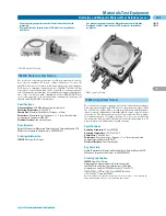
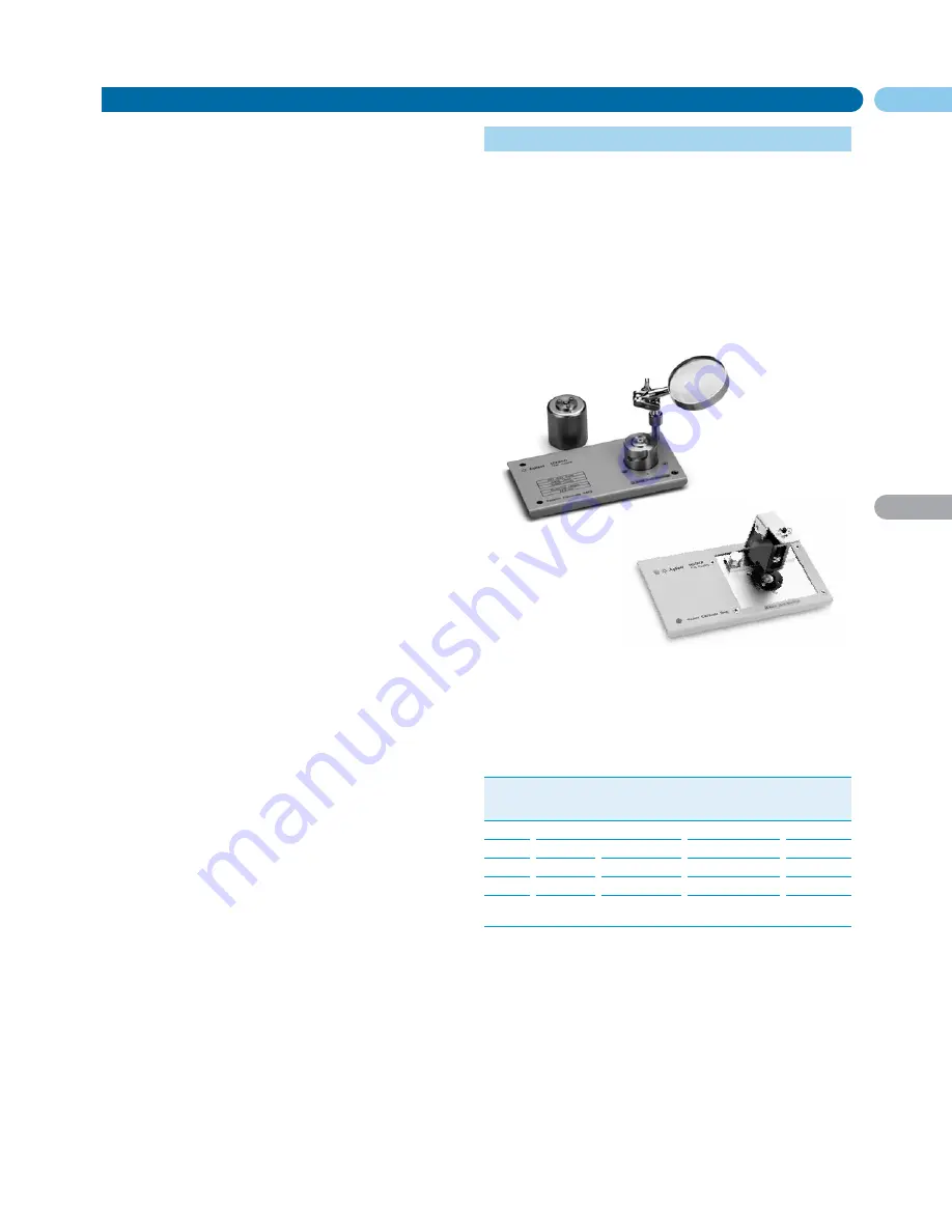
16196A/B/C/D Parallel Electrode SMD Test Fixtures
The 16196A, 16196B, 16196C and 16196D are coaxial-structured high
performance test fixtures for impedance measurements at frequen-
cies up to 3 GHz. These fixtures are your best choice for the character-
ization of parallel electrode chip inductors and other passive RF
components. The 16196A accommodates SMDs with the size code
1.6 mm x 0.8 mm. The 16196B handles SMDs that have the size code
1.0 mm x 0.5 mm. The 16196C is for size code 0.6 mm x 0.3 mm SMDs.
16197A
16196A/B/C/D
16197A Bottom Electrode SMD Test Fixture
The 16197A is designed for impedance evaluations of bottom elec-
trode SMDs components up to 3 GHz. This test fixture accommodates
various sizes of SMDs; as small as 0.6 mm x 0.3 mm (16197A-001) and
as large as 3.2 mm x 2.5 mm.
Key Specifications of Test Fixtures
Type of
Operating
Operating
Applicable
DUT Size
Fixture
Freq. (typ.)
Temperature
DUT Electrode
(l x w = mm)
Configuration
16196A
DC to 3 GHz –55°C to +85°C
Parallel electrodes
1.6 x 0.8 only
16196B
DC to 3 GHz –55°C to +85°C
Parallel electrodes
1.0 x 0.5 only
16196C
DC to 3 GHz –55°C to +85°C
Parallel electrodes 0.6 x 0.3 only
16196D
DC to 3 GHz –55°C to +85°C
Parallel electrodes 0.4 x 0.2 only
16197A
DC to 3 GHz –55°C to +85°C
Bottom electrodes
0.6 x 0.3 to
3.2 x 2.5
Key Literature
Accessories Selection Guide for Impedance Measurement, p/n 5965-4792E
Ordering Information
16196A
Parallel Electrode SMD Test Fixtures
16196A-710
Add a Magnifying Lens and Tweezers
16196B
Parallel Electrode SMD Test Fixtures
16196B-710
Add a Magnifying Lens and Tweezers
16196C
Parallel Electrode SMD Test Fixtures
16196C-710
Add a Magnifying Lens and Tweezers
16196D
Parallel Electrodes SMD Test Fixtures
16196D-710
Add a Magnifying Lens and Tweezers
16197A
Bottom Electrode SMD Test Fixtures
16197A-001
Add 0201 (inch)/0603 (mm) Device Guide Set
Summary of Contents for All
Page 1: ......


