Register-Based Programming 59
Appendix B
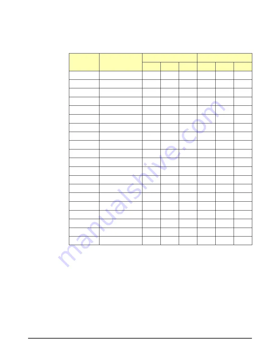
Table B-13 lists the Relay Module P1 connector pins and connection points
on P200 and P400.
Table B-13. Connector Pinouts
Relay Module
P1 Pins
Pin Names
(x is RMD number)
P200 pin numbers
P400 pin numbers
RMD0
RMD1
RMD3
RMD2
RMD4
RMD5
1
Ground
60
40
20
60
40
20
2
RMCx0
59
39
19
59
39
19
3
RMCx1
58
38
18
58
38
18
4
RMCx2
57
37
17
57
37
17
5
RMCx3
56
36
16
56
36
16
6
PWR2/PWR4
55
35
15
55
35
15
7
RMDx(11)
54
34
14
54
34
14
8
RMDx(10)
53
33
13
53
33
13
9
RMDx(9)
52
32
12
52
32
12
10
RMDx(8)
51
31
11
51
31
11
11
PWR2/PWR4
50
30
10
50
30
10
12
RMDx(7)
49
29
9
49
29
9
13
RMDx(6)
48
28
8
48
28
8
14
RMDx(5)
47
27
7
47
27
7
15
RMDx(4)
46
26
6
46
26
6
16
PWR2/PWR4
45
25
5
45
25
5
17
RMDx(3)
44
24
4
44
24
4
18
RMDx(2)
43
23
3
43
23
3
19
RMDx(1)
42
22
2
42
22
2
20
RMDx(0)
41
21
1
41
21
1
Artisan Technology Group - Quality Instrumentation ... Guaranteed | (888) 88-SOURCE | www.artisantg.com


