Chapter 1
15
Introduction
E2050 Hardware Description
E2050 Hardware Description
In addition to this guide, the E2050 product package consists of:
n
E2050 LAN/GPIB Gateway Front Panel
n
E2050 LAN/GPIB Gateway Rear Panel
n
AC/DC Adapter and Standard AC Power Cord
n
Rack Mount Kit (Optional)
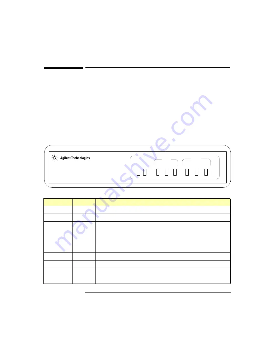
E2050 LAN/GPIB Gateway Front Panel
As shown in the following figure, the front panel of the Gateway contains
8 light-emitting diodes (LEDs) that indicate the status of the Gateway.
E2050 LAN/GPIB Gateway Front Panel
LED
Color
Meaning When Illuminated
Power
Green
Power is applied to the Gateway.
Fault
Red
Diagnostic failure of the hardware. This LED will normally be off.
LAN Conn
Yellow
A TCP/IP port is open (Telnet or a LAN connection). Flashes at a
fast rate for BOOTP or a BOOTP with TFTP configuration. Flashes
at a slow rate when the default IP address (
192.0.0.192
) is used
(after the
Config Preset
button is pressed).
LAN Tx
Yellow
Flashes at 10 Hz rate when transmitting packets on the LAN.
LAN Rx
Yellow
Flashes at 10 Hz rate when receiving packets from the LAN.
GPIB Talk
Yellow
The Gateway is configured to TALK on the GPIB bus.
GPIB Listen
Yellow
The Gateway is configured to LISTEN on the GPIB bus.
GPIB SRQ
Yellow
The GPIB SRQ line is asserted.
E2050 LAN GPIB
LAN/GPIB Gateway
Power Fail Conn Tx Rx Talk Listen SRQ
Summary of Contents for E2050
Page 1: ...Agilent E2050 LAN GPIB Gateway Installation and Configuration Guide ...
Page 2: ......
Page 10: ...10 ...
Page 11: ...11 1 Introduction ...
Page 23: ...23 2 Installation ...
Page 32: ...32 Chapter 2 Installation Installing the Hardware Notes ...
Page 33: ...33 3 Configuration ...
Page 63: ...63 4 Administration ...
Page 80: ...80 Chapter 4 Administration Configuring the Gateway Notes ...
Page 81: ...81 5 Troubleshooting ...
Page 99: ...99 A Specifications ...
Page 102: ...102 Specifications Specifications Notes ...
Page 103: ...103 Glossary ...
Page 111: ...Part Number E2050 90003 Printed in U S A E0701 E2050 90003 ...


