E2730A VXI RF TUNER
3-14
OPERATION
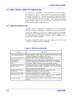
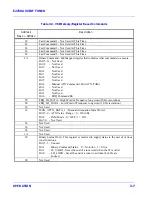
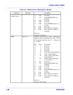
Table 3-8. Direct Memory Commands
Command
Response
Description
RMD nrf?
SMD nr1, nr1,
nr2,nr1,nr1,nr1,
nr1,nr1,nr1,nr1,
nr1,nr1,nr2,nr2,
nr2,nr1,nr2,nr2
Recall current tuner parameters from specified
memory channel.
Reset: SMD 001,0,0020.000,01,+00,1,0,
000,0,+000,-001,+00,0020.0000,2700.0000,
0000.1000,1,+0.00,+0000.0000
Example: SMD 001,0,1234.5678,01,+00,1,0,
024,0,+000,+005,+00,0002.0000,2700.0000,
0000.1000,0,+0.00,+0000.0000
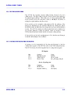
SMD nrf,nrf,
nrf,nrf,nrf,nrf,
nrf,nrf,nrf,nrf,
nrf,nrf,nrf,nrf,
nrf,nrf,nrf,nrf
Store directly to the specified memory channel the
following data list.
Field
Parameter
Range
1
Memory Channel Number
0,200
2
Idle Mode Status (IDM)
Ignored
3
Tuned Frequency (FRQ)
See FRQ
4
Bandwidth Slot (BWS)
Ignored
5
COR (COR)
Ignored
6
Detection Mode (DET)
Ignored
7
AGC Mode (AGC)
Ignored
8
Attenuation Setting (ATN)
0 to 60
9 AFC Mode (AFC)
Ignored
10
Pre Dwell (PDW)
Ignored
11
Signal Dwell (SDW)
Ignored
12 Loss Dwell (LDW)
Ignored
13
Sweep Start Freq. (FRA)
Ignored
14
Sweep Stop Freq. (FRB)
Ignored
15
Sweep Increment Freq. (INC) Ignored
16
Sweep Direction (SWD)
Ignored
17
BFO Frequency (BFO)
Ignored
18
IFO Frequency (IFO)
Ignored
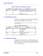
STORE AND RECALL
OPERATIONS
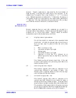
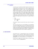
The Store and Recall memory operations allow the current tuner operating
parameters to be stored in a memory channel and allow the parameters
associated with a memory channel to be recalled as the current operating
parameters.
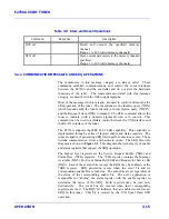
The Store (STO) command causes the current tuner parameters to be
stored in the memory channel specified. The Recall (RCE) command
causes the tuner to use the parameters of the specified memory channel for
current operations. The commands in this message category are listed in
Table 3-9
.
Summary of Contents for E2730A
Page 5: ...E2730A VXI RF TUNER iv LIST OF EFFECTIVE PAGES THIS PAGE INTENTIONALLY LEFT BLANK ...
Page 7: ...E2730A VXI RF TUNER vi REVISION RECORD THIS PAGE INTENTIONALLY LEFT BLANK ...
Page 12: ...1 i SECTION 1 GENERAL DESCRIPTION ...
Page 13: ...1 ii THIS PAGE INTENTIONALLY LEFT BLANK ...
Page 18: ...2 i SECTION 2 INSTALLATION ...
Page 19: ...2 ii THIS PAGE INTENTIONALLY LEFT BLANK ...
Page 32: ...3 i SECTION 3 OPERATION ...
Page 33: ...3 ii THIS PAGE INTENTIONALLY LEFT BLANK ...
Page 66: ...4 i SECTION 4 REPLACEMENT PARTS LIST ...
Page 67: ...4 ii THIS PAGE INTENTIONALLY LEFT BLANK ...
Page 71: ...E2730A VXI RF TUNER 4 4 REPLACEMENT PARTS LIST NOTES ...
Page 72: ...FP i FOLDOUTS ...

