E2730A VXI RF TUNER
3-18
OPERATION
07
06
05
ESB
04
MAV
03
02
01
00
N/U
*SRE
SRQ ENABLE
07
06
RQS
05
ESB
04
MAV
03
02
01
00
N/U
*STB?
STATUS BYTE
(
TABLE 3-10
)
&
&
07
PON
06
05
CME
04
EXE
03
DDE
02
QYE
01
00
OPC
*ESE
EVENT ENABLE
07
PON
06
05
CME
04
EXE
03
DDE
02
QYE
01
00
OPC
*ESR
EVENT STATUS
(
TABLE 3-10
)
07
2LOR
06
2LOT
05
1LO
04
FXE
03
02
01
00
DDE, CDE
DEV ERROR
(
TABLE 3-11
)
15
REF
14
BNI
13
12
EEF
11
N/U
10
09
EED
08
N/U
&
&
&
&
&
&
SRQ
O
R
N/U
N/U
N/U
N/U
N/U
N/U
N/U
N/U
N/U
N/U
N/U
N/U
N/U
N/U
N/U
N/U
N/U
N/U
N/U
99-0043
O
R
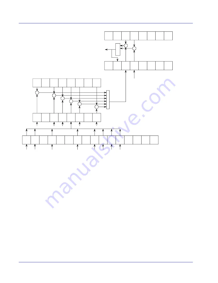
Figure 3-1. E2730A SRQ Structure Diagram
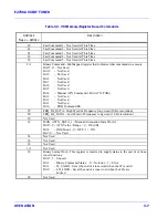
3.4.5 HARDWARE ERROR MESSAGES
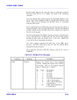
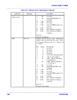
The E2730A performs both startup built-in internal tests and continuous
monitoring of key tuner sections. The tuner responds to a command which
reruns the startup test and also queries to determine the current status of
these operations along with the history since the last status request. The
errors indicated in these messages are all hardware errors and should not
occur as a result of normal operation. When the tuner detects one of these
errors the ERR LED on the front panel illuminates indicating the error
condition.
At startup the tuner verifies proper logic download and LO lock status.
The error status bits are set to indicate the results of startup tests.
Summary of Contents for E2730A
Page 5: ...E2730A VXI RF TUNER iv LIST OF EFFECTIVE PAGES THIS PAGE INTENTIONALLY LEFT BLANK ...
Page 7: ...E2730A VXI RF TUNER vi REVISION RECORD THIS PAGE INTENTIONALLY LEFT BLANK ...
Page 12: ...1 i SECTION 1 GENERAL DESCRIPTION ...
Page 13: ...1 ii THIS PAGE INTENTIONALLY LEFT BLANK ...
Page 18: ...2 i SECTION 2 INSTALLATION ...
Page 19: ...2 ii THIS PAGE INTENTIONALLY LEFT BLANK ...
Page 32: ...3 i SECTION 3 OPERATION ...
Page 33: ...3 ii THIS PAGE INTENTIONALLY LEFT BLANK ...
Page 66: ...4 i SECTION 4 REPLACEMENT PARTS LIST ...
Page 67: ...4 ii THIS PAGE INTENTIONALLY LEFT BLANK ...
Page 71: ...E2730A VXI RF TUNER 4 4 REPLACEMENT PARTS LIST NOTES ...
Page 72: ...FP i FOLDOUTS ...


