13
Hardware Installation
Typical System Configurations (cabling)
The following figures show examples of module and cable placement for various
configurations. Individual module configurations are described in detail starting on
.
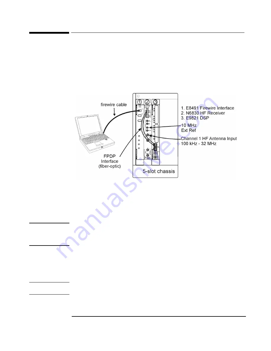
HF Search and Collection (N6830)
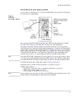
shows an N6830 HF receiver configuration in a 5-slot chassis (MFRAME1) that
provides HF search and collection in a small package.
Figure 1.
HF
search and collection
Data is passed to the E9821 DSP via the fiber-optic FPDP (front-panel data port) interface.
See
Fiber Optic Cabling of the DSP Module on page 28
for more information.
Depending on the PMC modules installed on the E9821 DSP board, this system can perform
search and provide 32 channels of narrowband channelization for collection. At least one 32-
channel digital downconverter (DDC, option 200) is required for narrowband channelization.
See
. Additional E9821 DSP boards can be added to the
system to provide additional narrowband channels.
Note
The typical E9821 DSP configuration for most signal types is one dual G4 processor (option
101) for each 32 channel digital downconverter (DDC, option 200). With this configuration,
each additional E9821 DSP module adds 64 digital downconverters for narrowband
channelization.
The block diagram for this configuration appears in
.
Installation of the controller and firewire interface is discussed on
Setting address switches:
• N6830 address settings appear on
.
• Switch settings for the E9821 are on
Note
Because of the heat generated by the DSPs, the FAN SPEED switch on the back of the 5-slot
and the E1421B 6-slot mainframes should always be set to HIGH.
Summary of Contents for E3238S
Page 62: ...62 Hardware Installation ...
Page 94: ...94 Software Installation and Configuration ...
Page 198: ...198 Application Resources ...
Page 218: ...218 Multi Channel Hardware Installation ...
Page 242: ...242 Specifications ...
Page 252: ...252 Appendix A d E3238s Listing E3238S Installation ...
Page 268: ...268 Appendix B d e3238s cfg Listing E3238S Installation ...


