background image

50

Hardware Installation

SI-9136B VHF/UHF Digital VME Tuner

If your system does not include an SI-9136B tuner, this procedure does not apply to your 

installation.
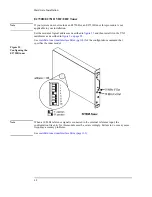
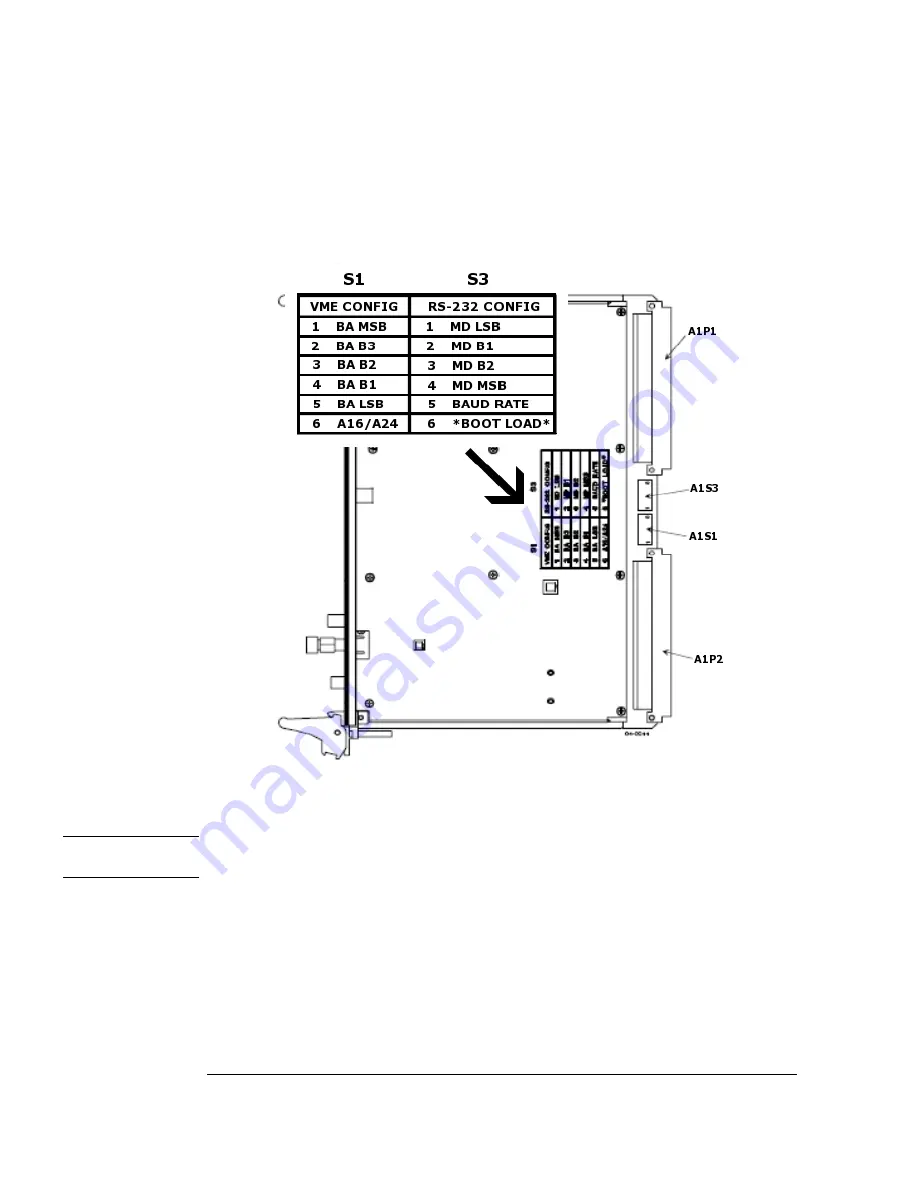
Set the module's VME address as described in 

figure 37

 and then install it in the VXI 

mainframe using the required VME/VXI carrier as described in 

figure 14 on page 26

.

Figure 37.
Configuring the 
SI-9136B tuner

The configuration file entry for this module is given on 

page 26

.

Note

For more details on VME Config and RS-232 switch settings, please consult the SI-9136B 

Manual.

Summary of Contents for E3238S

Page 1: ...iguration Reference Part Number E3238 90037 Software Version E3 4 Printed in U S A Print Date September 2011 Copyright Agilent Technologies Inc 1995 2011 All rights reserved 1615 75th Street SW Everett Washington 98203 6261 U S A ...

Page 2: ...marily provided to end user customers Agilent provides this customary commercial license in Software and technical data pursuant to FAR 12 211 Technical Data and 12 212 Computer Software and for the Department of Defense DFARS 252 227 7015 Technical Data Commercial Items and DFARS 227 7202 3 Rights in Commercial Computer Software or Computer Software Documentation Copyright 2001 2011 Agilent Techn...

Page 3: ... Cabling Dual Band configuration 27 Fiber Optic Cabling of the DSP Module 28 N6830 HF or VHF UHF Single Channel Configuration One DSP 29 N6830 HF or VHF UHF Dual Channel Configuration One DSP per Channel30 E1439D VHF UHF Configuration One DSP 31 VHF UHF Configuration Multiple DSPs with no Delay 32 VHF UHF Configuration Multiple DSPs with Delay 33 E1437A HF Configuration Multiple DSPs with Delay 34...

Page 4: ...tion File Update 64 Resource File Update 64 Updating Custom Libraries 64 For System Recovery 64 Controller Requirements 65 Setting the Compiler Environment Variables for option ASD 68 Installing and Configuring the E3238S Software 69 Configure the Operating System 70 Setup the Filesystem 70 Install the E3238S Program 71 Configuring the VXI interface 74 Restoring the Legacy IEEE Software Driver 74 ...

Page 5: ...guration 207 DSP Configuration 207 DSP Hardware Optimization 208 Synchronization 208 VHF UHF Configurations 209 2 channel N6830A V UHF Configuration 209 2 channel N6830A V UHF Configuration Settings 209 4 channel N6830A V UHF Configuration 211 2 channel N6830A V UHF Configuration Settings 211 3 channel E1439D V UHF Configuration 213 3 channel E1439D V UHF Configuration Settings 214 General Configu...

Page 6: ...ts and Outputs 232 Shielding Effectiveness 232 Software Features and Benchmarks 232 Specifications for 26 GHz PSA Systems 233 Frequency 234 Amplitude 235 Inputs and Outputs 236 Software Features and Benchmarks 236 General Specifications 237 Safety Summary 238 Safety Symbols and Instrument Markings 240 Service and Support 241 Index 243 Appendix A d E3238s Listing 251 Appendix B d e3238s cfg Listing...

Page 7: ...Development System This chapter contains the following topics Supported Components 8 Safety Notices 9 Hardware Installation Process 10 Typical System Configurations cabling 13 Fiber Optic Cabling of the DSP Module 28 Theory of Operation 35 Installing the System Controller 37 Configuring VXI Components 38 Tuner Configuration 45 Hardware Diagnostics 60 ...

Page 8: ... 051 16 0 TB 2U Disk Array EX2500A GigABit LAN I O Module Notes Most of the E3238S systems are integrated at the factory by Agilent Technologies This note describes the recommended system configurations For N6841A RF Sensor hardware and software installation refer to the documentation that came with the N6841A RF Sensor EMC filler panels must be installed in all empty VXI chassis slots This is nec...

Page 9: ...as been supplied in a safe condition The documentation contains information and warnings that must be followed by the user to ensure safe operation and to maintain the product in a safe condition For Safety and Regulatory information please refer to the General Specifications on page 237 and Safety Summary on page 238 of this manual ...

Page 10: ... B D E1439A B D N6830 VXI ADC page 39 E9821A VXI Signal Processing Module page 42 Cabling information begins on page 13 2 Edit the configuration file e3238s cfg so that it correctly defines the hardware installed All the commands that define hardware configuration are listed in the Hardware Configuration Reference on page 95 Note The E3238S passes IEC EN 61326 1 when the front cover and ground wir...

Page 11: ...non VXI tuner controlled by RS 232 interface connected to the E9821A DSP N6841A A small RF signal monitoring device housed in a weatherproof enclosure Tuner ADC Combinations Tuner driver names E1437A F1 F2 MHz IF BW MHz E1438 F1 F2 MHz IF BW MHz E1439 70 F1 F2 MHz IF BW MHz E1439 BB1 F1 F2 MHz IF BW MHz N6830 HF F1 F2 MHz IF BW MHz N6830 70 F1 F2 MHz IF BW MHz ADC Only 0 8 8 0 40 40 52 88 36 0 37 ...

Page 12: ...tor should be used to avoid overloading the ADC input 2 Option H70 is also supported but HY7 has better performance 3 Requires either the E2730B or the E2731B tuner 4 The range may be extended to 100 GHz by connecting the appropriate block down con verter to the CS5040 VXI module 5 The range may be extended to 100 GHz by connecting the appropriate block down con verter to the CS5040 VXI module ...

Page 13: ...on for collection At least one 32 channel digital downconverter DDC option 200 is required for narrowband channelization See DSP Configuration on page 36 Additional E9821 DSP boards can be added to the system to provide additional narrowband channels Note The typical E9821 DSP configuration for most signal types is one dual G4 processor option 101 for each 32 channel digital downconverter DDC opti...

Page 14: ...ll always override the searchRx1 adcClock parameter setting of the E3238S application started first Depending on the PMC modules installed on the E9821 DSP boards both instances of the E3238S can perform search and provide 32 channels of narrowband channelization for collection At least one 32 channel digital downconverter DDC option 200 is required for narrowband channelization See DSP Configurat...

Page 15: ...15 Hardware Installation Note Because of the heat generated by the DSPs the FAN SPEED switch on the back of the 5 slot and the E1421B 6 slot mainframes should always be set to HIGH ...

Page 16: ...required for narrowband channelization See DSP Configuration on page 36 E9821 DSP modules with option 200 can be added to 6 slot or 13 slot systems for additional narrowband channels The block diagram for this configuration appears in figure 22 on page 35 Installation of the controller and firewire interface is discussed on page 37 Setting address switches ADC address settings appear on page 39 Sw...

Page 17: ... provide 128 narrowband channels in a 5 slot mainframe Additional narrowband channels can be added by using a 6 slot or 13 slot mainframe and adding more E9821 DSP modules Note The typical E9821 DSP configuration for most signal types is one dual G4 processor option 101 for each 32 channel digital downconverter DDC option 200 With this configuration each additional E9821 DSP adds 64 digital downco...

Page 18: ...irst Depending on the PMC modules installed on the E9821 DSP boards both instances of the E3238S can perform search and provide 32 channels of narrowband channelization for collection At least one 32 channel digital downconverter DDC option 200 is required for narrowband channelization See DSP Configuration on page 36 Additional E9821 DSP boards can be added to 13 slot systems to provide additiona...

Page 19: ...ovide 32 channels of narrowband channelization for HF and 32 channels of narrowband channelization for V UHF At least one 32 channel DDC option 200 is required in each E9821for channelization See DSP Configuration on page 36 Additional E9821 DSP boards can be added to 6 or 13 slot VXI mainframes to provide additional narrowband channels Note The HF search and collection system and the V UHF search...

Page 20: ...e added to provide a maximum of 128 narrowband channels in a 5 slot mainframe Additional E9821 DSP boards can be added to 6 or 13 slot VXI mainframes to provide additional narrowband channels Note The typical E9821 DSP configuration for most signal types is one dual G4 processor option 101 for each 32 channel digital downconverter DDC option 200 With this configuration each additional E9821 DSP ad...

Page 21: ...ach 32 channel digital downconverter DDC option 200 With this configuration each additional E9821 DSP adds 64 digital downconverters for narrowband channelization The system above would have a total of 96 narrowband channels The block diagram for this configuration appears in figure 22 on page 35 Installation of the controller and firewire interface is discussed on page 37 Setting address switches...

Page 22: ... Switch settings for the E9821A are on page 42 The fiber optic interface between the ADC and the DSP requires two lines and must use port A on the E9821A See Fiber Optic Cabling of the DSP Module on page 28 The purpose of the figure above is to illustrate cabling The slots in which the tuner modules are installed or order of placement is not critical However when the searchRx adcDataPort page 141 ...

Page 23: ...AN connector light will illuminate The configuration file entries for this tuner are as follows searchRx1 tuner1 tunerModel PSA searchRx1 tuner1 tunerInterfaceParm 192 168 0 3 26500 0 45 0 9000 where 192 168 0 3 LAN IP address or hostname see next topic 26500 Stop Frequency 3000 to 50000 MHz 0 Freq Reference 0 Internal or 1 External 45 Settling Time 1 to 1000 mSec Typical 45 mSec 0 Option 1DS prea...

Page 24: ...t mask and the default gateway as shown 5 Click OK to finish Figure 11 E9821A LAN setup PSA LAN Setup To set the IP address for the PSA tuner Note The IP address for the PSA must be different than the IP address used for the E9821A The LAN cable provided with the PSA for firmware updates can not be used for this application 1 Press System Config I O IP Address and enter an address like 192 168 0 3...

Page 25: ...nfiguration file entries for this tuner are as follows searchRx1 tuner1 tunerModel SI9250 searchRx1 tuner1 tunerInterfaceParm 144 0 10 136 0 3 where 144 logical address of SI 9250 0 Reference input 0 int or ext 10MHz 1 ext 100MHz 10 SI 9250 settling time in ms 136 logical address of companion tuner E2730 31B 0 10MHz Ref input 0 internal 1 external 3 E273x settling time in milliseconds typically 3 ...

Page 26: ...e as follows searchRx1 tuner1 tunerModel SI9136 searchRx1 tuner1 tunerInterfaceParm 4096 1 0 0 5 3 0 400 searchRx2 tuner1 tunerModel SI9136 searchRx2 tuner1 tunerInterfaceParm 4096 2 0 0 5 3 0 400 where 0 to 48896 in steps of 2048 Typical 4096 VME Bus address 1 or 2 Channel 0 Independent 1 External 2 Slave LO Mode 0 Internal 1 External 10 MHZ Reference 2 MHz to 20 MHz Default 5 MHz Start Frequency...

Page 27: ...el SI9136 searchRx1 tuner1 tunerInterfaceParm 4096 1 0 0 5 3 0 400 The second configuration file entries for tuner 2 are as follows searchRx1 tuner1 tunerModel SI9136 searchRx1 tuner1 tunerInterfaceParm 4096 2 0 0 5 3 0 400 where 0 to 48896 in steps of 2048 Typical 4096 VME Bus address 1 or 2 Channel 0 Independent 1 External 2 Slave LO Mode 0 Internal 1 External 10 MHZ Reference 2 MHz to 20 MHz De...

Page 28: ...d in the section DSP Configuration page 36 The following paragraphs describe and show cabling for several configurations N6830 HF or VHF UHF Configuration one DSP Page 29 N6830 HF or VHF UHF Dual Channel Configuration one DSP per channel Page 30 E1439D VHF UHF Configuration one DSP Page 31 E1439D VHF UHF Configuration multiple DSPs with no delay Page 32 E1439D VHF UHF Configuration multiple DSPs w...

Page 29: ...the A section of serial ports on the E9821A DSP The connections are made so that each XMT socket connects to the other card s Rcv socket The first FPDP cable runs from the N6830 s Channel 1 XMT socket to the E9821A DSP s A section Rcv socket The second FPDP cable runs from the E9821A s A section XMT socket to the N6830 s Channel 1 Rcv socket Figure 16 FPDP Cables for N6830 Single Channel One DSP N...

Page 30: ...rst E9821A DSP s A section Rcv socket The second FPDP cable runs from the E9821A s A section XMT socket to the N6830 s Channel 1 Rcv socket The third FPDP cable runs from the N6830 s Channel 2 XMT socket to the second E9821A DSP s A section Rcv socket The fourth FPDP cable runs from the second E9821A s A section XMT socket to the N6830 s Channel 2 Rcv socket Figure 17 FPDP Cables for Dual Channel ...

Page 31: ...nections are made so that each XMT socket connects to the other card s Rcv socket The first FPDP cable runs from the ADC s XMT socket to the DSP s A section Rcv socket the second FPDP cable runs from the DSP s A section XMT socket to the ADC s Rcv socket Figure 18 FPDP Cables for VHF UHF One DSP No Delay For configuring multiple DSPs with no Delay see VHF UHF Configuration Multiple DSPs with no De...

Page 32: ...cket is connected to the second DSP s A section Rcv socket The second DSP s A section XMT socket loops back to the ADC s FPDP RCV socket Figure 19 FPDP Cables for VHF UHF Two or Three DSPs The lower part of figure 19 shows a three DSP configuration The ADCs XMT socket connects to the first DSP s A section Rcv socket The first DSP s A section XMT socket is connected to the second DSP s A section Rc...

Page 33: ...FPDP serial ports Again the connections are made so that each XMT socket connects to the other card s Rcv socket Figure 20 FPDP Cables for VHF UHF Multiple DSPs Delay Configurations Three DSPs with Delay The next configuration has one E1439D ADC and three E9821A DSP modules configured for search and a delay As shown in lower configuration of figure 20 a pair of cables run from the ADC s Serial FPD...

Page 34: ...connections are made so that each XMT socket connects to the other card s Rcv socket The communications between the E1437A ADC and the first DSP occurs on the local bus Figure 21 FPDP Cables for HF Two or Three DSPs Delay Configuration Three DSPs with Delay The next configuration has one E1437A ADC and three E9821A DSP modules configured for search and a delay The communications between the E1437A...

Page 35: ... 70 MHz IF ADC Time Capture The ADC FIFO buffer may be used to collect time snapshot data The size of the buffer depends on the ADC model and the options in it For example the E1439D ADC has a 1 GB RAM option that serves the purpose Handoff Receivers As many as 100 handoff receivers can be managed by the E3238S system These may be VXI modules on the VXIbus or connect via RS232 LAN GPIB etc Time Re...

Page 36: ...ble configuration for one E9821A module The configurations are determined by two things The types of modules installed on the E9821A provide the functional blocks The library software determines how the data flows between the modules Figure 23 E9821 configuration examples for search and signal processing Figure 23 shows two configurations On the left is a search S configuration optimized for sweep...

Page 37: ...ardware Installation Installing the System Controller The laptop controller uses a firewire interface to connect to the VXI mainframe as shown in figure 26 Figure 26 Laptop controller and firewire interface ...

Page 38: ... the following pages 3 Check the connectors at the back of the VXI mainframe they must have RFI boots installed around the connectors to meet performance specifications 4 Firmly seat the modules in the VXI Mainframe with the ADC in the slot immediately to the left of the E9821A 5 Secure the modules by tightening the captive screws that hold each module into the mainframe This must be done to insur...

Page 39: ...ront panel error LED which will blink in the following circumstances 1 The selected VXI logical address is not valid 0 254 255 are invalid The LED will be lit continuously 2 An internal error such as an unlocked PLL has occurred The LED will blink 3 times per second 3 An external reference is programmed but the reference PLL is not locked or no external signal is present or the external reference ...

Page 40: ...odule The N6830A module only supports FPDP adcMasterClock Off On Auto Specifies whether the ADC puts its clock signal on the VXI backplane for use by other modules Only one ADC may drive the VXI backplane If the Auto mode is selected the adcMasterClock for the search ADC is turned Off unless the searchRxConfiguration is set to a multiple channel mode In this case the first ADC is set to On and the...

Page 41: ...chRx1 adcDataPort FPDP Increasing the ADC sample rate may affect the sweep rate depending on the search setup number of averages and RBW selections searchRx1 adcModel E1439D 70 searchRx1 adcInterfaceParm 130 searchRx1 adcClock Internal searchRx1 adcDataPort FPDP searchRx1 adcMasterClock Auto ...

Page 42: ...ort should be set to provide command control bits 1 and 2 set to 1 LAN The LAN port is used for development debugging service trouble shooting and to control the PSA tuner See page 24 Power and cooling limits The E9821A is a carrier for PMC and ePMC plug in boards There are four sites for ePMC boards Due to power and cooling limitations no more than three1 dual G4 processing boards may be installe...

Page 43: ...o the E1472A except that it has 75Ω connections Note Only one switch module may installed in a system The e3238s cfg default configuration file contains the commands to implement the switch configuration shown above To enable this configuration just remove the comment characters in the first column of these commands This module may also be used to implement multiple tuners see searchRx tuner tuner...

Page 44: ...onsists of the switch driver board the switches and an extender module It may be ordered as special option 404 E3238B Cabling for four antennas into one tuner is shown above bc350 357VXI C Time and Frequency Processor IRIG This VXI module provides accurate time stamp information The model bc357VXI also has a GPS satellite receiver for a source This module may be installed in any chassis slot Set t...

Page 45: ...er to the E9821A and a 50Ω BNC IF signal cable that connects the tuner to the ADC See figure 33 1 Turn power off Turn the power to the RF tuner off and disconnect the power cord before installing or configuring the 89431A to avoid damage 2 Set the baud rate jumper If the system was integrated at the factory skip this step and proceed to step 3 Before the 89431A RF tuner can be used in the E3238S s...

Page 46: ...ve 4 Connect the IF signal cable The 89431A RF tuner is connected to the ADC module by a 50Ω BNC cable included in the AFU kit a Attach one end of the BNC cable to the front panel connection on the 89431A RF tuner labeled OUT to channel 1 b Attach the other end of the BNC cable to the front panel connection on the ADC module labeled Analog In 5 Reconnect the power cable This concludes the hardware...

Page 47: ...llation Configure the modules as described in figure 34 and then install them in the VXI mainframe as described in figure 9 Set the logical address of the LO module to 140 Set the logical address of the RF module to 142 See searchRx tuner tunerInterfaceParm pg 162 for the configuration command that specifies the tuner model Figure 34 Configuring the WJ9119 1 tuner ...

Page 48: ...in the VXI mainframe as described in figure 9 on page 22 See searchRx tuner tunerInterfaceParm pg 162 for the configuration command that specifies the tuner model Figure 35 Configuring the E2730B tuner Note When a 10 MHz reference signal is connected to the external reference input the configuration file entry for this module must be set accordingly Failure to do so may cause frequency accuracy pr...

Page 49: ...scribed in figure 36 and then install it in the VXI mainframe as described in figure 13 on page 25 Figure 36 Configuring the SI 9250 tuner The configuration file entry for this module is given on page 25 VXI address 144 E1407A A B to C Size Adapter cover cut away to show tuner SI 9250 2 downconverter 1 position 0 position 128 64 32 16 8 4 2 1 Jumper pins 1 and 2 to enable VXI Addressing 1 2 3 4 ...

Page 50: ...the module s VME address as described in figure 37 and then install it in the VXI mainframe using the required VME VXI carrier as described in figure 14 on page 26 Figure 37 Configuring the SI 9136B tuner The configuration file entry for this module is given on page 26 Note For more details on VME Config and RS 232 switch settings please consult the SI 9136B Manual ...

Page 51: ...by two instances of the E3238S software in a Dual Band configuration This configuration allows collection in two different RF frequency bands Figure 38 Dual Tuners with 2 E3238S Instances The diagram in figure 39 illustrates the SI 9136B in a 2 search receiver configuration In this configuration both receivers are tuned to the same frequency Figure 39 Dual Tuners in a 2 Search Receiver Configurati...

Page 52: ...52 Hardware Installation Communication Solutions CS 5040 Microwave Tuner This tuner is used with the E1439A B D ADC as shown in figure 9 on page 22 Figure 40 Configuring the CS 5040 tuner ...

Page 53: ...ration file for Agilent 35688E Option WRP Wideband Recording and Playback Subsystem The following text assumes that the Agilent E3238S Signal Detection and Monitoring Solutions is installed in the default directory C E3238S To use the Agilent 35688E Option WRP Wideband Recording and Playback Subsystem the LAN interface must be enabled in the DSP module so that the DSP module auto recognizes the di...

Page 54: ...specified in the configuration file for example searchRx1 minDelayTimeRequired 0 5 If delay is not being used the FPDP cables are connected as shown in the Agilent E3238S Installation and Configuration Reference in the VHF UHF Single Channel Configuration Multiple DSPs with no Delay section except the ADC connection is connected to Port 2 of the recorder In this configuration sFPDP Port B on the A...

Page 55: ... 100 and set the netmask to 255 255 0 0 LAN Configuration Recorder Agilent E9821 DSP Other Device for example PSA Spectrum Analyzer If the configuration includes another LAN device such as an Agilent E444x PSA being used as a tuner a networking hub or switch must be used The hub or switch will create a private network that is typically isolated from all other LANs For this configuration set the IP...

Page 56: ...ule s settings can be configured using the module s web page Discovering the EX2500A module s IP Address To discover the EX2500A module on the local network 1 Click Window s START button 2 Select Agilent IO Libraries Suite Agilent Connection Expert 3 Select your PC s name from the instuments 4 From the System Tasks menu click Add an interface 5 In the Manually Add an interface dialog box click VXI...

Page 57: ...utton to and verify that the LEDs on the front of the EX2500A are flashing to test the connection 9 Click Cancel 10 In the VXI Technologies LXI VXI Slot 0 Interface dialog box click the IP address option button and note the IP address displayed Note It is a good idea to make a note of the EX2500A module s IP address You will need to have it available to set the module s options after you have clos...

Page 58: ... The VTI Technologies EX2500A GigABit I O LAN module can be configured to Static or Auto IP addressing It is generally easier to use the module when it is configured for a static IP address The following steps describe how to set the proper IP address mode 14 Click the Web Interface button on the right hand side of the screen to open a web browser window with the IP address shown in the Agilent Co...

Page 59: ...59 Hardware Installation 17 In the group of controls labeled IP Source click to clear the AutoIP selection 18 Close the web browser 19 Exit the Agilent Connection Expert ...

Page 60: ...ram a window appears as shown in figure 41 Figure 41 Agilent eVxiTest application This utility identifies and performs a power on test on all VXI modules found in the VXI mainframe Click Run to perform a self test on all modules with self test capability Units with self tests have the word Test in their Self Test field Click Help Overview for more eVxiTest information Note Halt any program that ac...

Page 61: ... the mainframe such as the logical address and attributes See Configuring the VXI interface page 74 To start it click Start Programs Agilent IO Libraries Suite Utilities Visa assistant Figure 42 Agilent Visa Assistant Compare the addresses here with the entries in the e3238s cfg file Also check the E3238S File Shared Libraries dialog box to determine which e3238s cfg file is used ...

Page 62: ...62 Hardware Installation ...

Page 63: ...ndle most installation issues automatically The minimum and recommended controller requirements are listed in Controller Requirements page 65 For Upgrades To upgrade the E3238S software from a previous version just run the setup exe program see Installing and Configuring the E3238S Software page 69 This procedure should handle most installation issues automatically N6841A RF Sensor For software an...

Page 64: ...urce file in use E3238s Updating Custom Libraries It may be necessary to recompile any custom libraries which you have created An upgrade note describing the details should accompany the material sent as an upgrade kit New versions of libraries purchased from Agilent should be delivered to you on separate CDs as part of the upgrade For System Recovery To recover the system from something like repl...

Page 65: ...20 GB 400MB required for installation of E3238S SW 120 GB 400MB required for application software SCSI or Raid0 faster for snapshots Floppy Disk Drive Not required by E3238S system May be required for system recovery boot floppies 1 44MB Floppy Drive May be required for system recovery boot floppies DVD Drive DVD drive Needed to install E3238S software and License file 16x DVD RW Used to install a...

Page 66: ...Not required for basic operation of E3283S system Required to control GP IB handoff receivers 1 port May use LAN to GPIB converter Required to control GP IB HP IB handoff receivers Keyboard Mouse Not required for Laptops PS 2 or USB required for other controllers If USB make sure you have enough USB ports Not required for Laptops PS 2 or USB required for other controllers If USB make sure you have...

Page 67: ...et for manipulation of data and or report creation Microsoft Office Word Excel Win2K or XP Use Export of E3238S databases to a spreadsheet for manipulation of data and or report creation Microsoft Visual Studio Not required for basic operation of E3283S system Visual Studio net Use User Programming ASD and Signals Development Wind River DIAB Compiler Not required for basic operation of E3283S syst...

Page 68: ... Visual Studio Installation If you have already installed Visual Studio 6 Visual Studio NET Ver 7 0 or Visual Studio NET Ver 8 0 you may need to run the batch file provided to set the environment variables This can be found in the Visual Studio Installation path in these locations depending on your version The following information assumes the Microsoft Software is installed on the C drive Visual ...

Page 69: ...erface 74 Installing Software Options 79 Software Licensing 80 The steps to complete these actions are described in the following procedures This section describes the installation and configuration process onto a laptop running the Windows XP Professional operating system The procedures are similar on a system running Windows 2000 Server Note The E3238S installation will check for necessary IO li...

Page 70: ... Tools Folder Options 7 Click the View tab 8 Under Advanced settings enable Show hidden files and folders 9 Make sure that Hide file extensions for known file types is disabled 10 Click OK to close the Folder options dialog box Setup the Filesystem This procedure creates the folders for the E3238S software Agilent recommends copying an image of the E3238S DVD to the computer s C drive Placing the ...

Page 71: ...nd display an opening screen You may also choose to run the installation from C Images E3238S E3 2 Winnt Setup exe 2 From the Installation screen click Install 35688E now read the next screen and click Next 3 Select your hardware platform The instructions that follow are for the VXI hardware platform Please refer to the installation documentation for your hardware platform if you select anything o...

Page 72: ...h and the E3238S installation should resume If it doesn t re start the E3238S installation following the instructions in step 1 7 If the Exceed X Server is not present on your system you will be prompted to install the Exceed X server 1 8 Click Yes to install the Exceed X Server Software 9 Once the Exceed installation is complete the E3238S installation should continue automatically If it doesn t ...

Page 73: ...Click OK and proceed with the installation You will reboot the system when all of the software has been installed 11 Click Finish to complete the E3238S installation 12 The E3238S installation will then provide a simple VXI test called eVxiTest to check that your hardware is accessible It is recommended that you install this test 13 Click Finish to complete the installation You will be prompted to...

Page 74: ... software driver To restore the legacy IEEE 1394 software driver use the procedure Restoring the Legacy IEEE Software driver If you are installing the E3238S software on a previous version of Microsoft Windows you can skip this procedure Restoring the Legacy IEEE Software Driver 1 In Microsoft Windows 7 click the START button and select Command Prompt from the program menu 2 In the Command Prompt ...

Page 75: ...nd the VXI mainframe Note If the IEEE 1394 adapter card was just installed the Found New Hardware Wizard may open If the Found New Hardware Wizard opens click Next and when it is finished click Finish 2 Run Connection Expert Click the IO Control icon in the task bar then click Agilent Connection Expert Or click Start All Programs Agilent IO Libraries Suite Agilent Connection Expert Connection Expe...

Page 76: ...puter recognized all the modules in your VXI mainframe expand VXI0 in the Instrument I O on this PC section Connection Expert will list all the modules and their addresses A green check mark is shown to verify the VXI mainframe and modules are on and connected properly The E8491 will always show a red x Figure 45 IO Config 4 In order to use the E3238S Software with your configured IO Devices you m...

Page 77: ...the resulting Resource Manager dialog box You start it from the Agilent IO Control You apply or cycle VXI mainframe power You press the E8491 Reset button You reboot your PC In VXI systems with multiple E8491 interfaces you can turn off individual VXI mainframes without affecting other mainframes in the system When a mainframe is turned on the VXI Resource Manager re configures that mainframe For ...

Page 78: ...drivers provided on the E3238S installation disc The drivers are found in the installation disc directory winnt E8491B The compressed diver files for the EX2500A are DRIVER_32BIT_EX2500A_R2P4P0 zip DRIVER_64BIT_EX2500A_R2P4P0 zip Also included is a readme file named ReadMe_EX2500A txt Connect the Ethernet cable from the computer to the EX2500A VXI module in the mainframe Power on the computer and ...

Page 79: ... band recorder option NBR is installed in E3238s NBR To enable a library a Using a text editor open the configuration file E3238s e3238s cfg b Scroll to the bottom of the file c Remove the exclamation points preceding the appropriate command lines controlling the desired library d Enter the appropriate arguments to the setup commands Follow the instructions given in the ReadMe file to properly con...

Page 80: ...oftware license uses a USB key the USB key must be disconnected from the computer until after the E3238S application software has been installed The first time the USB Key is connected to a USB port Windows runs the New Hardware Found wizard This wizard associates the USB Key with the correct software drivers From a License CD If you have received a license file CD then install the E3238S software...

Page 81: ...make sure that you have the correct USB Key connected securely in the computer s USB port Compare the serial number listed in the license file with the number on the USB Key If the license is keyed to a specific computer make sure that the correct computer is being used To do this 1 Run the HostID utility Start Programs Agilent E3238S HostID This displays the computer s host ID pairs of numbers se...

Page 82: ...e software to be installed and run on various PCs by moving the key to the new PC Verifying the computer s hostID This option locks the software to one host computer This is the simplest method when the software can be locked to a single computer Note The software runs only when the license file is properly installed and the corresponding hostID is present A computer keyed license locks the softwa...

Page 83: ...3238S software is used for training or demonstration purposes it may be provided with a temporary license Temporary licenses can be identified by the suffix temp lic in their names When a long term license is installed the temporary license should be deleted or re named with a filename extension other than lic This action prevents the temporary license from interfering with the E3238S software rec...

Page 84: ...he key is installed in a different USB port If the key is removed while the software is running within a few minutes the software displays an error message This message notifies the user that the license that allows the E3238S software to run is no longer valid When this message is displayed the software provides a 10 minute grace period to save mission data and setup files before shutting down Go...

Page 85: ... of the USB Key The failure or loss of the original USB Key disables the licensing on this kind of system Computer key based licensing relies on a computer identification which is derived from its hardware components The failure or removal of the components used to characterize it will disable the licensing on such a system USB key Recovery If the USB Key fails notify the E3238S license administra...

Page 86: ...ation of the E3238S software for a limited time1 whether the original key mechanism was USB key based or computer key based This provides temporary license recovery for situations where you are unable to contact the license administration team at the time of the failure and when you need your system to be back up and running in a very short period of time 1The length of time that the backup key wi...

Page 87: ...rdware On computer keyed systems make sure that the license file s hostID shown both in the file name and in the file text matches one of the hostID values found in the file C temp e3238sHostID text file written by the HostID utility program To run this utility program click Start Programs Agilent E3238S HostID When the license is locked to a USB Key make sure that you have the correct key plugged...

Page 88: ...r more information about hardware configuration and the definitions used in the e3238s cfg file see Hardware Installation on page 7 and Hardware Configuration Reference on page 95 Upgrades When upgrading E3238S software new features may not work properly until the new configuration information is specified in the old e3238s cfg file If you are installing the upgrade over the previous version i e t...

Page 89: ...c user place the modified E3238s file in the user s Profile directory C WINNT Profiles user_name or in the user s HOME directory as defined in the Windows User Manager The resource file in the E3238S directory e g C E3238s applies to all users that do not have a resource file in their Profile or HOME directories When the application is started the window manager searches a number of places until i...

Page 90: ...blank passwords to console logon only When this is disabled user accounts that have no password can recover the secured display without entering a password Access Control Security The E3238S application supports control of access to entries in the main menu bar and popup menus by a system administrator See the dialog box called by File Access Control Only the items enabled in this dialog box may b...

Page 91: ...238S uvad voice activity detector VHF UHF E3238S pager pager intercept E3238S audio audio output uses DDC channels PC audio output E3238S featureStudio used to develop feature extraction energy filter libs E3238S nbr narrow band recorder Network Services To support networked communication between the E3238S application and external socket programs there must be an entry in the C WINNT system32 dri...

Page 92: ...rom one installation to the next the label E3238S is used to indicate the application s home directory in the following discussion The include and shared library files are installed in the following directories E3238S include include files E3238S lib shared library files The User Programming example source files are organized under the examples directory Each User Programming shared library type h...

Page 93: ... dll HOME asd userMenu userMenuArrow dll userPane HOME asd userPane userPane dll genericLib HOME asd genericLib genericLib dll 3 Install a personal copy of the E3238S application resource file and modify it copy E3238S d E3238s HOME E3238s Note that this copies the file and renames it Edit the resource file and add the following line specifying the hardware configuration file to load when the appl...

Page 94: ...94 Software Installation and Configuration ...

Page 95: ...options such as option USD provide their own configuration file that can be cut and pasted into the e3238s cfg file The configuration files are located in the directory for the specific option For example the USD configuration file default location is C E3238s usd d e3238s cfg Note The N6841A RF Sensor has its own configuration file Refer to the documentation that came with the N6841A RF Sensor fo...

Page 96: ... 142 searchRx adcMasterClock 143 searchRx adcModel 144 searchRx adcSampleRate 145 searchRx antenna calFile 146 searchRx antenna switchCmnd 147 searchRx antenna switchMask 148 searchRx dspCmndPort 149 searchRx dspDataCompression 150 searchRx dspDataPort 151 searchRx dspModel 152 searchRx dspModules 153 searchRx dspNoHardwareConfig 154 searchRx minDelayTimeRequired 155 searchRx snapshotMemory interf...

Page 97: ...71 signal hostDsp 172 signal hostLib 173 signal loadFactor 174 signal maxChannels 175 signal minChannels 176 signal targetDsp 177 socketServer 178 socketServerTimerInterval 179 timeCorrectionMaxBlocksize 180 timeReference 181 timeReferenceCal 182 timerInterruptInterval 183 userAlarmTask 184 userMenu 185 userPane 186 userThreshold 187 vxiInterface 188 ...

Page 98: ...ary Example multipleSignalsPerProcessor Enabled asxDsp_0 C E3238s downloadables ASXdsp_0 elf asxDsp_1 C E3238s downloadables ASXdsp_1 elf Demo Signal Type signal1 enabled False signal1 hostLib C E3238S demo demoHost dll signal1 hostDsp C E3238S demo demoDsp dll signal1 targetDsp C E3238S demo demoDsp esl signal1 loadFactor 64 signal1 minChannels 4 signal1 maxChannels 32 signal1 args signal1 alias ...

Page 99: ...rary Example multipleSignalsPerProcessor Enabled asxDsp_0 C E3238s downloadables ASXdsp_0 elf asxDsp_1 C E3238s downloadables ASXdsp_1 elf Demo Signal Type signal1 enabled False signal1 hostLib C E3238S demo demoHost dll signal1 hostDsp C E3238S demo demoDsp dll signal1 targetDsp C E3238S demo demoDsp esl signal1 loadFactor 64 signal1 minChannels 4 signal1 maxChannels 32 signal1 args signal1 alias...

Page 100: ...ternate name to be used in the application s user interface so that the real signal name is not displayed Example Direction Finding df1 enabled False df1 hostLib C E3238s lib demoDF dll df1 args df1 alias NorthPole df1 latitude df1 longitude df1 declination df1 heading Note You may use either regular slashes or back slashes in the pathname ...

Page 101: ...ecifies the values for any parameters that a custom library might pass in Example Direction Finding df1 enabled False df1 hostLib C E3238s lib demoDF dll df1 args 45 90 135 180 360 df1 alias NorthPole df1 latitude df1 longitude df1 declination df1 heading Note You may use either regular slashes or back slashes in the pathname ...

Page 102: ...e North Values are entered as decimal values This parameter may be changed in the GUI Example Direction Finding df1 enabled False df1 hostLib C E3238s lib demoDF dll df1 args df1 alias NorthPole df1 latitude 47 21 df1 longitude 75 42 df1 declination 15 2 df1 heading 80 0 See Also df heading EDF page 104 df latitude EDF page 106 df longitude EDF page 107 Note This parameter is saved as part of the ...

Page 103: ...ines associated with it Another way to disable a signal library is to leave the setting True and just comment out the signal enabled line Example The following example shows a DF library that is disabled Direction Finding df1 enabled False df1 hostLib C E3238s lib demoDF dll df1 args df1 alias NorthPole df1 latitude 47 21 df1 longitude 75 42 df1 declination 15 2 df1 heading 80 0 Note You may use e...

Page 104: ...e entered as decimal values This parameter be changed in the GUI Example Direction Finding df1 enabled False df1 hostLib C E3238s lib demoDF dll df1 args df1 alias NorthPole df1 latitude 47 21 df1 longitude 75 42 df1 declination 15 2 df1 heading 80 0 See Also df declination EDF page 102 df latitude EDF page 106 df longitude EDF page 107 Note This parameter is saved as part of the mission state in ...

Page 105: ...ibrary to be loaded in the host system controller This provides the host component of the typical host target interaction mechanism Example Direction Finding df1 enabled False df1 hostLib C E3238s lib demoDF dll df1 args df1 alias NorthPole df1 latitude df1 longitude df1 declination df1 heading Note You may use either regular slashes or back slashes in the pathname ...

Page 106: ...his may be changed in the GUI Example Direction Finding df1 enabled False df1 hostLib C E3238s lib demoDF dll df1 args df1 alias NorthPole df1 latitude 47 21 df1 longitude 72 45 df1 declination df1 heading See Also df declination EDF page 102 df heading EDF page 104 df longitude EDF page 107 Note This parameter is saved as part of the mission state in the current group If you recall a mission stat...

Page 107: ...e the Western Hemisphere Example Direction Finding df1 enabled False df1 hostLib C E3238s lib demoDF dll df1 args df1 alias NorthPole df1 latitude 47 21 df1 longitude 75 42 df1 declination df1 heading See Also df declination EDF page 102 df heading EDF page 104 df latitude EDF page 106 Note This parameter is saved as part of the mission state in the current group If you recall a mission state of a...

Page 108: ...spaces separate the values Example The following commands disable user control of one entry in the File menu and all entries in the Edit menu disableAccess Secure Display disableAccess Log Files disableAccess Clear Log disableAccess Clear Log File disableAccess Clear Energy History disableAccess Clear Signal Database disableAccess Clear Frequency Lists disableAccess Clear Audio Output disableAcces...

Page 109: ...e ADC and its own DSP assets such that given a set of sweep search parameters provided by the host it returns spectral data To perform this task it requires an operating system and the measurement program that are downloaded from the host controller This command specifies the DSP program file to be downloaded when the application starts Example The following command defines the downloadable file d...

Page 110: ...y look like this e3238s 7011 tcp The default value of this parameter is e3238s Example The following commands show an example socket configuration e3238sService e3238s e3238sServiceMaxConnections 4 e3238sServiceDataBufferSize 512 e3238sServiceSendBufferSize 0 e3238sServiceRecvBufferSize 0 See Also e3238sServiceDataBufferSize page 111 e3238sServiceMaxConnections page 112 e3238sServiceRecvBufferSize...

Page 111: ...e default value of this parameter is 512 Example The following commands show an example socket configuration e3238sService e3238s e3238sServiceMaxConnections 4 e3238sServiceDataBufferSize 512 e3238sServiceSendBufferSize 0 e3238sServiceRecvBufferSize 0 See Also e3238sService page 110 e3238sServiceMaxConnections page 112 e3238sServiceRecvBufferSize page 113 e3238sServiceSendBufferSize page 114 maxCl...

Page 112: ...verSockets Example The following commands show an example socket configuration e3238sService e3238s e3238sServiceMaxConnections 4 e3238sServiceDataBufferSize 512 e3238sServiceSendBufferSize 0 e3238sServiceRecvBufferSize 0 Figure 47 Socket connection process See Also e3238sService page 110 e3238sServiceDataBufferSize page 111 e3238sServiceRecvBufferSize page 113 e3238sServiceSendBufferSize page 114...

Page 113: ... value used to match the conditions The default value for Windows is 8192 Example The following commands show an example socket configuration e3238sService e3238s e3238sServiceMaxConnections 4 e3238sServiceDataBufferSize 512 e3238sServiceSendBufferSize 0 e3238sServiceRecvBufferSize 0 See Also e3238sService page 110 e3238sServiceDataBufferSize page 111 e3238sServiceMaxConnections page 112 e3238sSer...

Page 114: ...for this parameter is 0 which allows the system to adjust the actual value used to match the conditions The default value for Windows is 8192 Example The following commands show an example socket configuration e3238sService e3238s e3238sServiceMaxConnections 4 e3238sServiceDataBufferSize 512 e3238sServiceSendBufferSize 0 e3238sServiceRecvBufferSize 0 See Also e3238sService page 110 e3238sServiceDa...

Page 115: ... length is 255 characters Description Used to restore access to features within the E3238S application that have been restricted through use of the disableAccess page 108 You can also choose to just comment out the disableAccess lines in the e3238s cfg file See Also disableAccess page 108 ...

Page 116: ...as 16 filter definitions may be loaded but no more than 5 of each type pre or post may be active at a time Notes If a library contains code for both features and filters use the same name with both commands Either regular slashes or back slashes may be used in the pathname Example energyHistoryFilter e3238s filterBUTCH dll e3238s filterSUNDANCE dll featureExtraction e3238s featureBUTCH dll e3238s ...

Page 117: ... raw spectral search data Example featureExtraction e3238s featureBUTCH dll e3238s featureSUNDANCE dll As many as 4 feature shared libraries may be loaded each of which may define as many as 4 features Note If one shared library program contains code for both features and filters use the same name with both commands Note You may use either regular slashes or back slashes in the pathname See Also e...

Page 118: ...ers Description Specifies a shared library comprising features that do not belong in any of the specific user defined categories such as panes feature types feature filters alarm tasks and signal processing As many as four generic shared libraries may be loaded Example genericLib C e3238s examples doItAll dll ...

Page 119: ...controlled by the E3238S system The number 16 that appears in the syntax above is determined by the maxHandoffRxs parameter setting in the E3238s resource file An error occurs when you specify more than this setting Example The following commands define the hardware configuration for a handoff receiver handoffRx1 driver C e3238s lib HD_8607 dll handoffRx1 interface rs232 COM1 9600 handoffRx1 label...

Page 120: ...rmined by the maxHandoffRxs parameter setting in the E3238s resource file An error occurs when you specify more than this setting Example The following commands define the hardware configuration and driver program for a handoff receiver handoffRx1 driver C e3238s lib HD_8607 dll handoffRx1 interface rs232 COM1 9600 handoffRx1 label VHF UHF Rx Note When using a controller with a firewire interface ...

Page 121: ...as 100 handoff receivers may be controlled by the E3238S system The number 16 that appears in the syntax above is determined by the maxHandoffRxs parameter setting in the E3238s resource file An error occurs when you specify more than this setting Example handoffRx1 driver C e3238s lib HD_8607 dll handoffRx1 interface rs232 COM1 9600 handoffRx1 label VHF UHF Rx See Also handoffRx label page 121 ha...

Page 122: ...le length between the IRIG source and this system Units are integers where each increment is equivalent to 100 ns 10e 7 s Note This selection has no effect when timeReference page 181 is systemClock Example timeReference vxiIRIG irigModel bc350vxi irigInterfaceParm 200 irigOperatingMode Decode irigTimeCodeFormat IRIGB irigTimeCodeModulation AM irigClock Internal irigSecondsFromGMT 0 irigCableDelay...

Page 123: ...ernal means the onboard crystal oscillator is used as the time clock This oscillator may be stabilized with a crystal oven External means the signal on the front panel 10 MHz SMB connector is used as the time clock Note This selection has no effect when timeReference page 181 is systemClock Example timeReference vxiIRIG irigModel bc350vxi irigInterfaceParm 200 irigOperatingMode Decode irigTimeCode...

Page 124: ...e See the Hardware Installation section for information on configuring the module switches Note This selection is ignored when timeReference page 181 is systemClock Example timeReference vxiIRIG irigModel bc350vxi irigInterfaceParm 200 irigOperatingMode Decode irigTimeCodeFormat IRIGB irigTimeCodeModulation AM irigClock Internal irigSecondsFromGMT 0 irigCableDelay 0 ...

Page 125: ...I Time and Frequency Processor TFP by Datum Inc is the only IRIG time reference module supported Note This selection has no effect when timeReference page 181 is systemClock Example timeReference vxiIRIG irigModel bc350vxi irigInterfaceParm 200 irigOperatingMode Decode irigTimeCodeFormat IRIGB irigTimeCodeModulation AM irigClock Internal irigSecondsFromGMT 0 irigCableDelay 0 ...

Page 126: ...eerun means the TFP generates time values using the clock specified with the irigClock page 123 command 1PPS means the TFP synchronizes to the signal on the 1PPS front panel input pin 14 of J1 RealtimeClock means the TFP synchronizes to the onboard real time clock RTC that is battery backed This mode is not recommended when a crystal oven is installed because the RTC accuracy is less than that of ...

Page 127: ... to get GMT All time stamp values are given in GMT When the system time reference signal is a local time this parameter may be used to derive GMT such that time_ref irigSecondsFromGMT GMT Example timeReference vxiIRIG irigModel bc350vxi irigInterfaceParm 200 irigOperatingMode Decode irigTimeCodeFormat IRIGB irigTimeCodeModulation AM irigClock Internal irigSecondsFromGMT 0 irigCableDelay 0 ...

Page 128: ...Format B 100 PPS code Reference IRIG document 200 95 NASA36 specifies NASA 36 bit one second time code 2137 specifies 25 PPS one second time code 1 kHz Same as XR3 with 100 Hz symbol rate XR3 specifies 25 PPS one second time code 250 Hz 100 Hz symbol rate Note This selection is relevant only when irigOperatingMode page 126 is Decode Example timeReference vxiIRIG irigModel bc350vxi irigInterfacePar...

Page 129: ...on PCM specifies pulse code modulation or DC level shift DCLS This modulation type is not supported when irigTimeCodeFormat page 128 is 2137 or XR3 Note This selection is ignored when timeReference page 181 is systemClock Example timeReference vxiIRIG irigModel bc350vxi irigInterfaceParm 200 irigOperatingMode Decode irigTimeCodeFormat IRIGB irigTimeCodeModulation AM irigClock Internal irigSecondsF...

Page 130: ...ing This setting has no impact on the e3238sServiceMaxConnections parameter described on page 112 Example socketServer Disabled maxServices 1 maxClientSockets 0 socketServerTimerInterval 5 Figure 48 Socket connection process See Also maxServices page 131 socketServer page 178 socketServerTimerInterval page 179 e3238sService page 110 e3238sServiceDataBufferSize page 111 e3238sServiceMaxConnections ...

Page 131: ...rvices implemented through user defined shared library programs Example socketServer Disabled maxServices 1 maxClientSockets 0 socketServerTimerInterval 5 Figure 49 Socket connection process See Also maxClientSockets page 130 socketServer page 178 socketServerTimerInterval page 179 e3238sService page 110 e3238sServiceDataBufferSize page 111 e3238sServiceMaxConnections page 112 e3238sServiceRecvBuf...

Page 132: ...te name to be used in the application s user interface so that the real signal name is not displayed Example Modulation Recognition modRec1 enabled False modRec1 hostLib C E3238s mr1 mr1 dll modRec1 args modRec1 alias Bob Note You may use either regular slashes or back slashes in the pathname See Also modRec args EMR page 133 modRec enabled EMR page 134 ...

Page 133: ...n Specifies the values for any parameters that a custom library might pass in Example Modulation Recognition modRec1 enabled False modRec1 hostLib C E3238s mr1 mr1 dll modRec1 args modRec1 alias Bob Note You may use either regular slashes or back slashes in the pathname See Also modRec alias EMR page 132 modRec enabled EMR page 134 ...

Page 134: ...all the lines associated with it Another way to disable a signal library is to leave the setting True and just comment out the signal enabled line Example The following example shows a signal that is disabled Modulation Recognition modRec1 enabled False modRec1 hostLib C E3238s mr1 mr1 dll modRec1 args modRec1 alias Bob Note You may use either regular slashes or back slashes in the pathname See Al...

Page 135: ...the filename of the Mod Rec library to be loaded in the host system controller This provides the host component of the typical host target interaction mechanism Example Modulation Recognition modRec1 enabled False modRec1 hostLib C E3238s mr1 mr1 dll modRec1 args modRec1 alias Bob Note You may use either regular slashes or back slashes in the pathname ...

Page 136: ...e multiSystemSyncTimeout EMS Syntax multiSystemSyncTimeout integer 1 integer 60 Description Specifies the time in seconds to wait for system synchronization acknowledgment in a multi system configuration Example multiSystemSyncTimeout 5 ...

Page 137: ...tiSystemSynchronization EMS Syntax multiSystemSynchronization enum enum Off Master Slave Description Specifies whether the system is either a master or slave system Example multiSystemSynchronization Master or multiSystemSynchronization Slave ...

Page 138: ...ignalsPerProcessor Enabled asxDsp_0 C E3238S downloadables ASXdsp_0 elf asxDsp_1 C E3238S downloadables ASXdsp_1 elf searchRx1 minDelayTimeRequired 0 Demo Signal Type signal1 enabled False signal1 hostLib C E3238S demo demoHost dll signal1 hostDsp C E3238S demo demoDsp dll signal1 targetDsp C E3238S demo demoDsp esl signal1 loadFactor 64 signal1 minChannels 4 signal1 maxChannels 32 signal1 args Se...

Page 139: ... for each channel Example searchRxConfiguration MultiChannelParallelTimeSynchronousSearch numSearchRx 2 searchRx1 adcModel E1439B 70 searchRx1 adcInterfaceParm 130 searchRx1 adcClock Internal searchRx1 adcDataPort localBus searchRx1 adcMasterClock Auto searchRx2 adcModel E1439B 70 searchRx2 adcInterfaceParm 131 searchRx2 adcClock Internal searchRx2 adcDataPort localBus searchRx2 adcMasterClock Aut...

Page 140: ...s Ext Clock connector as a clock for the sample rate This signal may be generated by a source in the system e g a downconverter s LO Ref or may come from a source outside the system E1437A 10 24 MHz E1438A B E1439A B D 10 MHz N6830A 10 0 MHz Master or 5 0 MHz Slave The WJ9119 HF LO module provides an accurate clock signal from its ADC CLK outputs which can be used as a reference for the E1437A ADC...

Page 141: ...by side since data cannot flow through an empty slot FPDP front panel data port is a serial fiber optic interface that may be used when both the ADC and the DSP modules support it The FPDP throughput is much greater than that of the Local Bus The FPDP interface is supported on the E1438B D E1439B D and the N6830A ADCs and the E9821A DSP When the FPDP port is used both the receive Rx and transmit T...

Page 142: ... address used to communicate with the ADC module in the search receiver This address must correspond with switches set inside the module Example The following commands define the hardware configuration for the ADC in the search receiver searchRx1 adcModel E1437A searchRx1 adcInterfaceParm 130 searchRx1 adcClock Internal See Also Tuner Configuration page 45 ...

Page 143: ...d with the Note Only one ADC may drive the VXI backplane clock line at a time Off specifies that the search ADC s clock signal is not put on the VXI backplane On specifies that the search ADC s clock signal is put on the VXI backplane Auto specifies that the search ADC s clock is put on the VXI backplane The clock is used by the DDCs in the channelizer system Example The following commands define ...

Page 144: ... BB baseband N6830A HF fs 81 92 MHz span 32 MHz N6830A 70 fs 95 MHz span 36 MHz B models have the fiber optic front panel data port FPDP C models have no Local Bus or FPDP interfaces and are not recommended D models are the same as the B model with improved phase noise performance The E1439 has a 70 MHz IF input but may also be used in baseband mode The IF input allows it to be used with the E2730...

Page 145: ...Stare Bandwidth 81920000 32 MHz 40960000 16 MHz 20480000 8 MHz 10240000 4 MHz N6830A 70 Sample Rate Stare Bandwidth 95000000 36 MHz 47500000 18 MHz 23750000 9 MHz 11875000 4 5 MHz If you are upgrading from a 9119 1 tuner with E1437 ADC to an N6830A HF use the following settings searchRx1 adcModel N6830A HF searchRx1 adcSampleRate 20480000 searchRx1 adcDataPort FPDP Increasing the ADC sample rate m...

Page 146: ...data to be used for a given antenna Example These commands control the application of corrections to compensate for tuner response and antenna path response These user supplied corrections are in addition to built in RF and IF corrections For an example of the file format see the file e3238s cal d tuner1 cal Cal files are normally located in the C E3238s cal searchRx1 antenna1 calFile antenna1 cal...

Page 147: ...nd and switchMask as shown for antennas 1 2 and 8 in the following example searchRx1 antenna1 switchCmnd 0x00000000 searchRx1 antenna1 switchMask 0x0000F00F searchRx1 antenna2 switchCmnd 0x00000002 searchRx1 antenna2 switchMask 0x0000F00F searchRx1 antenna8 switchCmnd 0x00002080 searchRx1 antenna8 switchMask 0x0000F0F0 01 02 03 00 COMM 00 Bank 0 11 12 13 10 COMM 10 Bank 1 21 22 23 20 COMM 20 Bank ...

Page 148: ...am the RF multiplex switch which allows antenna switching It is used in conjunction with searchRx antenna switchCmnd page 147 to minimize relay activity and maximize switch contact life Example searchRx1 antenna1 switchCmnd 0x00010001 searchRx1 antenna1 switchMask 0x000F000F searchRx1 antenna2 switchCmnd 0x00010002 searchRx1 antenna2 switchMask 0x000F000F ...

Page 149: ...i directional VXI bus on the VME backplane This has been the default command port for VXI modules up to now This bus may also be used to move the DSP output data to the host controller Example The following commands define the hardware configuration for the search receiver DSP module searchRx1 dspModel E9821A searchRx1 dspModules 128 searchRx1 dspNoHardwareConfig 222D searchRx1 dspCmndPort VXI sea...

Page 150: ...igh resolution settings low RBW values when DSP is not the limiting factor Multiple search channels supported by option EMC When used with a collection subsystem having many narrow band channels Or you want to add more channels to an existing system that is already IO bound The disadvantages When performance is limited by the DSP processing resources such as with a large number of averages and a h...

Page 151: ...sing the bi directional VXI bus on the VME backplane This has been the default command port for VXI modules up to now This bus may also be used to move the DSP output data to the host controller Example The following commands define the hardware configuration for the search receiver DSP module searchRx1 dspModel E9821A searchRx1 dspModules 128 searchRx1 dspNoHardwareConfig 222D searchRx1 dspCmndPo...

Page 152: ...e searchRx1 dspModel E9821A searchRx1 dspModules 128 129 searchRx1 dspNoHardwareConfig 222D searchRx1 dspCmndPort VXI searchRx1 dspDataPort VXI searchRx1 dspDataCompression On downloadable C E3238s downloadables e9821a out Note For multi channel systems that have multiple ADC s sharing one E9821A DSP searchRx2 dspModel searchRx3 dspModel and so on should be set to Shared See Also The configuration...

Page 153: ... information on setting the module switches This defines all the DSP modules in the system even though they may perform narrow band signal processing that is not technically part of the search receiver Example searchRx1 dspModel E9821A searchRx1 dspModules 128 129 searchRx1 dspNoHardwareConfig 222D searchRx1 dspCmndPort VXI searchRx1 dspDataPort VXI searchRx1 dspDataCompression On downloadable C E...

Page 154: ...ardwre mode E empty 1 single G4 processor option 110 2 dual G4 processor option 100 D DDC digital downconverter option 200 Example searchRx1 dspModules 128 129 searchRx1 dspNoHardwareConfig 222D E2DE This example illustrates two DSP modules configured as follows at logical address 128 site 1 dual G4 processor site 2 dual G4 processor site 3 dual G4 processor site 4 32 channel DDC at logical addres...

Page 155: ...C channels and G4 processors that are installed The amount of delay required is typically determined by calculating the time needed to detect the energy and verify that the signal is the correct type Delay is provided by buffering the wideband data in memory on a processor card in front of a DDC card See figure 25 on page 36 The minimum delay set in the default config file is 0 seconds and disable...

Page 156: ...pport the continued use of previously purchased units Example The following command defines a snapshot module in the e3238s cfg file searchRx1 snapshotMemory1 model E9830A searchRx1 snapshotMemory1 interfaceParm 133 The example above defines the configuration of one E9830A Snapshot module shown in figure 51 Because it s input is the VXI Local Bus it must be installed between the ADC and the DSP mo...

Page 157: ...n parameter is provided to support the continued use of previously purchased units Example The following command defines a snapshot module in the e3238s cfg file searchRx1 snapshotMemory1 model E9830A searchRx1 snapshotMemory1 interfaceParm 133 The example above defines the configuration of one E9830A module as shown in the block diagram in figure 52 Because it s input is the VXI Local Bus it must...

Page 158: ...th is 31 characters Description This command is used to program the VXI multiplex switch It specifies the string to appear in the Switch Configuration dialog with the label Configuration Example The following command represents a switch configuration with 16 inputs from antennas and 1 output searchRx1 switchConfiguration 16 1 ...

Page 159: ...le The following example contains variables A1 A2 that are replaced automatically when an antenna name is defined searchRx1 switchInterfaceParm 131 searchRx1 switchConfiguration 16 1 searchRx1 switchConnections A1 A2 To 40 A3 A4 A5 A6 To 41 A7 A8 A9 A10 To 42 A11 A12 A13 A14 To 43 A15 A16 From Com 00 From Com 10 To Tuner From Com 20 From Com 30 Note This example show the lines indented so that it ...

Page 160: ...ger 1 integer 254 Description Specifies the VXI logical address of the RF switch module The range specified above applies to VXI logical addresses The address must correspond with switches set inside the module Example searchRx1 switchInterfaceParm 131 See Also The Hardware Installation section of this book ...

Page 161: ...locks may be added E1474A is a 75Ω RF switch with 6 4 1 blocks to which additional blocks may be added E1368A is a microwave switch that provides as many as 5 switches 3 internal and 2 external for signal frequencies from DC to 18 GHz E1369A is a microwave switch for which individual switch relays may be selected and installed to provide as many as 5 switches 3 internal and 2 external for signal f...

Page 162: ...255 settle time steps 7 5 MHz in microseconds default is 500 settle time steps 7 5 MHz in microseconds default is 500 Output parameters specify which outputs are enabled on the LO front panel The valued entered is a mask for which outputs are enabled For example 1 Enable output 1 7 Enable output 1 2 and 3 255 Enable all outputs E2730B E2731B A VHF UHF tuner that is a VXI module see page 48 searchR...

Page 163: ... tunerModel HP89431A searchRx1 tuner3 tunerInterfaceParm 125000 searchRx1 tuner4 tunerModel Off Models Supported None is baseband operation which uses the span of the ADC 89431A is a non VXI 2 2 650 MHz tuner with an RS 232 interface WJ9119 1 is a VXI 0 5 32 MHz tuner IF BW 8 MHz use with E1437A ADC E2730A B is a VXI 20 2700 MHz tuner use with E1439A B D ADC only E2731A B is a VXI 20 6000 MHz tune...

Page 164: ...ommand setting 01 02 03 00 COMM 00 Bank 0 11 12 13 10 COMM 10 Bank 1 21 22 23 20 COMM 20 Bank 2 32 31 30 33 COMM 30 E1472A E1474A RF Switch Bank 3 42 41 40 43 COMM 40 Bank 4 52 51 50 53 COMM 50 Bank 5 5 4 3 2 1 0 Bank Number 00 01 02 03 10 11 12 13 XXXX XXXX XXXX XXXX XXXX XXXX 0 00 0 00 0000 0000 0000 0000 20 21 22 23 30 31 32 33 40 41 43 50 51 53 42 52 1 1 0x440000 tuner3 tunerSwitchCmnd 40 Tune...

Page 165: ...onjunction with searchRx tuner tunerSwitchCmnd page 164 to limit the number of switch relay changes needed to select a specified tuner This maximizes the switch contact reliability and life Example searchRx1 tuner1 tunerSwitchCmnd 0x110000 searchRx1 tuner1 tunerSwitchMask 0xFF0000 searchRx1 tuner2 tunerSwitchCmnd 0x220000 searchRx1 tuner2 tunerSwitchMask 0xFF0000 ...

Page 166: ...on data to be used for a given tuner Example These commands control the application of corrections to compensate for tuner response and antenna path response These user supplied corrections are in addition to built in RF and IF corrections For an example of the file format see the file e3238s cal d tuner1 cal Cal files are normally located in the C E3238s cal searchRx1 tuner1 userCalFile tuner1 ca...

Page 167: ...aster ADC to the slave ADCs VXIBackplane specifies that the signals are passed on bus lines at the rear of the mainframe ADCFrontPanel specifies that the signals are passed through the ADC front panel connectors as shown in figure 56 Figure 56 ADC front panel clock and sync connections Mainframe Extender ECL Sync Clock Mainframe Extender ECL Sync Clock Mainframe Extender ECL Sync Clock Note use of...

Page 168: ...es SingleChannelSearch is the common operation type in which one channel sweeps MultiChannelParallelTimeSynchronousSearch is the mode in which multiple search receiver channels sweep the same regions and sampling is time synchronous MultiChannelParallelPhaseSynchronousSearch is the mode in which multiple search receivers sweep the same regions and the measurement results are phase synchronous Note...

Page 169: ...SignalsPerProcessor Enabled asxDsp_0 C E3238s downloadables ASXdsp_0 elf asxDsp_1 C E3238s downloadables ASXdsp_1 elf Demo Signal Type signal1 enabled False signal1 hostLib C E3238S demo demoHost dll signal1 hostDsp C E3238S demo demoDsp dll signal1 targetDsp C E3238S demo demoDsp esl signal1 loadFactor 64 signal1 minChannels 4 signal1 maxChannels 32 signal1 args 21 45 A friday signal1 alias Bob N...

Page 170: ...led asxDsp_0 C E3238s downloadables ASXdsp_0 elf asxDsp_1 C E3238s downloadables ASXdsp_1 elf Demo Signal Type signal1 enabled False signal1 hostLib C E3238S demo demoHost dll signal1 hostDsp C E3238S demo demoDsp dll signal1 targetDsp C E3238S demo demoDsp esl signal1 loadFactor 64 signal1 minChannels 4 signal1 maxChannels 32 signal1 args 21 45 A friday signal1 alias Bob Note You may use either r...

Page 171: ... comment out the signal enabled line Example The following example shows a signal that is disabled multipleSignalsPerProcessor Enabled asxDsp_0 C E3238s downloadables ASXdsp_0 elf asxDsp_1 C E3238s downloadables ASXdsp_1 elf Demo Signal Type signal1 enabled False signal1 hostLib C E3238S demo demoHost dll signal1 hostDsp C E3238S demo demoDsp dll signal1 targetDsp C E3238S demo demoDsp esl signal1...

Page 172: ...he E3238S application in the noHardware mode Example multipleSignalsPerProcessor Enabled asxDsp_0 C E3238s downloadables ASXdsp_0 elf asxDsp_1 C E3238s downloadables ASXdsp_1 elf Demo Signal Type signal1 enabled False signal1 hostLib C E3238S demo demoHost dll signal1 hostDsp C E3238S demo demoDsp dll signal1 targetDsp C E3238S demo demoDsp esl signal1 loadFactor 64 signal1 minChannels 4 signal1 m...

Page 173: ...chanism Example multipleSignalsPerProcessor Enabled asxDsp_0 C E3238s downloadables ASXdsp_0 elf asxDsp_1 C E3238s downloadables ASXdsp_1 elf Demo Signal Type signal1 enabled False signal1 hostLib C E3238S demo demoHost dll signal1 hostDsp C E3238S demo demoDsp dll signal1 targetDsp C E3238S demo demoDsp esl signal1 loadFactor 64 signal1 minChannels 4 signal1 maxChannels 32 signal1 args 21 45 A fr...

Page 174: ...ors and the signal processing hardware assets installed Example The following example shows a load factor of 64 channels per processor multipleSignalsPerProcessor Enabled asxDsp_0 C E3238s downloadables ASXdsp_0 elf asxDsp_1 C E3238s downloadables ASXdsp_1 elf Demo Signal Type signal1 enabled False signal1 hostLib C E3238S demo demoHost dll signal1 hostDsp C E3238S demo demoDsp dll signal1 targetD...

Page 175: ...e following example shows a maximum number of channels of 32 multipleSignalsPerProcessor Enabled asxDsp_0 C E3238s downloadables ASXdsp_0 elf asxDsp_1 C E3238s downloadables ASXdsp_1 elf Demo Signal Type signal1 enabled False signal1 hostLib C E3238S demo demoHost dll signal1 hostDsp C E3238S demo demoDsp dll signal1 targetDsp C E3238S demo demoDsp esl signal1 loadFactor 64 signal1 minChannels 4 s...

Page 176: ... with each as well as the number of DDC channels and G4 processors that are available in the installed hardware Example The following example shows a minimum number of channels of 4 multipleSignalsPerProcessor Enabled asxDsp_0 C E3238s downloadables ASXdsp_0 elf asxDsp_1 C E3238s downloadables ASXdsp_1 elf Demo Signal Type signal1 enabled False signal1 hostLib C E3238S demo demoHost dll signal1 ho...

Page 177: ...sp_1 commands are not used Example multipleSignalsPerProcessor Enabled asxDsp_0 C E3238s downloadables ASXdsp_0 elf asxDsp_1 C E3238s downloadables ASXdsp_1 elf Demo Signal Type signal1 enabled False signal1 hostLib C E3238S demo demoHost dll signal1 hostDsp C E3238S demo demoDsp dll signal1 targetDsp C E3238S demo demoDsp esl signal1 loadFactor 64 signal1 minChannels 4 signal1 maxChannels 32 sign...

Page 178: ...ample The following commands show an example socket configuration socketServer Enabled maxServices 1 maxClientSockets 0 socketServerTimerInterval 5 See Also maxClientSockets page 130 maxServices page 131 socketServerTimerInterval page 179 e3238sService page 110 e3238sServiceDataBufferSize page 111 e3238sServiceMaxConnections page 112 e3238sServiceRecvBufferSize page 113 e3238sServiceSendBufferSize...

Page 179: ...conds Default value is 5 ms Example The following commands show an example socket configuration socketServer Enabled maxServices 1 maxClientSockets 0 socketServerTimerInterval 5 See Also maxClientSockets page 130 maxServices page 131 socketServer page 178 e3238sService page 110 e3238sServiceDataBufferSize page 111 e3238sServiceMaxConnections page 112 e3238sServiceRecvBufferSize page 113 e3238sServ...

Page 180: ...me Correction processing is enabled time snapshot files larger than this value will not be corrected If not specified this defaults to 16 Mega samples Time correction processing is performed on the host computer and is memory intensive requiring 8 bytes for each sample This value can be increased if large corrected capture files are needed but the host computer should have adequate physical memory...

Page 181: ...m clock or an IRIG time reference module as the time reference source This is the reference for all time stamp values Example timeReference vxiIRIG irigModel bc350vxi irigInterfaceParm 200 irigOperatingMode Decode irigTimeCodeFormat IRIGB irigTimeCodeModulation AM irigClock Internal irigSecondsFromGMT 0 irigCableDelay 0 See Also irigModel page 125 ...

Page 182: ... sample clock generated timestamps to track IRIG time Only applies with tuner locked and vxiIRIG timeReference Example timeReference vxiIRIG timeReferenceCal 0 irigModel bc350vxi irigInterfaceParm 200 irigOperatingMode Decode irigTimeCodeFormat IRIGB irigTimeCodeModulation AM irigClock Internal irigSecondsFromGMT 0 irigCableDelay 0 ...

Page 183: ... handoff receivers and narrow band signal processing channels When a signal processing library is loaded this specifies how often in milliseconds the E3238S system is interrupted to handle messaging between the host and target processes The default is 100 ms Great care should be used in selecting this value Values too small inhibit the search process E3238S and values too large may cause the signa...

Page 184: ...serAlarmTask filename The maximum length is 511 characters Description Specifies the user defined alarm task shared library program to load Example userAlarmTask C e3238s userTaskEmail dll Note You may use either regular slashes or back slashes in the pathname ...

Page 185: ...ifies the user defined menu shared library program to load As many as 4 user defined menu bar entries may be defined each with as many as 8 menu entries Example userMenu C e3238s examples userMenu userMenu dll C e3238s examples userMenu userMenuArrow dll Note You may use either regular slashes or back slashes in the pathname ...

Page 186: ...e user defined shared library that implements a custom window pane The maximum number of user defined panes allowed is 4 To display a pane add it to the application window with the layout pane type command Example userPane C e3238s examples userPane userPane sl Note You may use either regular slashes or back slashes in the pathname ...

Page 187: ...dware Configuration Reference userThreshold Syntax userThreshold filename The maximum length is 511 characters Description Specifies the user defined shared library that implements a custom threshold algorithm ...

Page 188: ...iption This command identifies the VISA1 name for the VXI system as it is defined in the controller software See Configuring the VXI interface page 74 The default name is VXI0 zero 1VISA Virtual Instrument Software Architecture is an I O library that provides a program ming interface to VXIplug play instrument drivers ...

Page 189: ...ion about Motif resources see one of the many Motif references available such as X Toolkit Intrinsics Programming Manual Volume Four of the X Window Series by O Reilly Associates When you first install the software no resource file exists Instead a file named d E3238s is created in the e3238s directory d is for default This avoids overwriting an existing file when the installation is really an upd...

Page 190: ...log view Each handoff requires approximately 90 bytes of memory Example alarmLogViewLength 400 audioOutput type XmRString default 0 Specifies the location of the audio output The default is the same location that the e3238s code is executing on clientTitles type Boolean default False Specifies whether to put titles on dialog boxes commandHelpVolume type XmRString default commandHelpVolume E3238s_h...

Page 191: ...00 0 37 5 k 55 k 95 k 12 500 0 18 8 k 28 k 48 k 6 250 0 9 4 k 14 k 24 k 3 125 0 4 7 k 6 9 k 12 k 1 562 5 2 4 k 3 5 k 6 k 781 25 1 2 k 1 7 k 3 k 390 625 590 870 1 5 k 195 3125 300 440 750 97 6563 150 220 380 48 8281 80 110 190 24 4141 37 60 100 12 2070 18 27 50 6 1035 9 2 14 23 E1439 BB E1439 70 N6830 70 ADC 95 MSamples Sec Shape Factor Bin Spacing 9 0 1 4 0 1 2 6 1 742 187 5 1 1 M 1 6 M 2 8 M 371 ...

Page 192: ...default wav Specifies the default extension for audio files The possible audio extensions are u MuLaw u law al ALaw A law au Sun NeXT wav Microsoft RIFF waveform snd Next l16 Linear16 16 bit signed l8 Linear8 8 bit signed lo8 Linear8Offset 8 bit unsigned displayLocalTime type Boolean default True Specifies whether time information is displayed using the local timezone information When False time v...

Page 193: ... font used by spreadsheet area of the handoff receiver pane hideDisplay type Boolean default False Prevents the software from displaying an X window Error messages are displayed See also remoteMode pg 195 help4helpVolume type XmRString default Help4Help Specifies the help volume that provides help for help helpVolume type XmRString default E3238S_home help e3238s Specifies the help volume Note Win...

Page 194: ...g default red Specifies the color of the trace ID displayed when an ADC overload occurs If no value is set the trace ID color does not change when an overload condition occurs ownColormap type Boolean default False Enables the software to use its own colormap This is useful when there are not enough colors available in the system colormap On computers that have a dual hardware colormap system it w...

Page 195: ...ximum number of signal database entries allowed When this maximum number of entries is reached no new entries are recorded spectrogramBackingStoreSize type Integer default 100000 Specifies the amount of memory in bytes to use for storing the spectrogram and color spectrogram display This is used when the spectrogram needs to be redisplayed such as when a dialog box is removed from being on top of ...

Page 196: ...Wrap type Boolean default False Specifies whether the toolbar icons wrap to a new row or truncate at the end of a single row of icons To allow sizing of the toolbar pane when toolbarWrap is True the resource toolbar paneMaximum should be increased to view the maximum number of rows tooltips type Boolean default True Specifies whether to display the toolbar tooltips traceBackgroundColor type XmRStr...

Page 197: ...ion keys as follows F2 to do a frequency full scale F3 to do a amplitude auto scale F4 to turn the marker on F5 to turn the marker off F6 to do both an amplitude and frequency auto scale transientTitles type Boolean default False Specifies whether to put titles on transient dialog boxes useHardware type Boolean default True Specifies whether or not to use the VXI hardware When True energy data is ...

Page 198: ...198 Application Resources ...

Page 199: ...is chapter describes the installation and configuration of measurement hardware for Option EMC multi channel search Option EMC is only available with the E3238S 35688E Signal Intercept and Collection System Option EMC is not available with the E3238S N6820E Signal Survey Software ...

Page 200: ... data from the ADC s to the E9821A The E1437 ADC data actually flows through the ADCs to the E9821A as shown in figure 58 For the E1437 HF solution the data path is the VXI Local Bus so the ADCs must be installed adjacent to each other in the mainframe Figure 58 Block diagram showing actual data flow Time Synchronous Measurements All channels in a multi channel search system are inherently time sy...

Page 201: ...ltiChannelParallelTimeSynchronousSearch numSearchRx 2 searchRx1 dspModel E9821A searchRx1 dspModules 128 searchRx1 dspCmndPort VXI searchRx1 dspDataPort VXI searchRx1 dspDataCompression On searchRx2 dspModel Shared searchRxAdcSynchronization ADCFrontPanel searchRx1 adcModel N6830A HF searchRx1 adcInterfaceParm 64 searchRx1 adcDataPort FPDP_NO_CHECK searchRx1 adcClock Internal searchRx1 adcMasterCl...

Page 202: ...chRx1 dspModel E9821A searchRx1 dspModules 128 searchRx1 dspCmndPort VXI searchRx1 dspDataPort VXI searchRx1 dspDataCompression On searchRx2 dspModel Shared searchRx3 dspModel Shared searchRx4 dspModel Shared searchRxAdcSynchronization ADCFrontPanel searchRx1 adcModel N6830A HF searchRx1 adcInterfaceParm 64 searchRx1 adcClock Internal searchRx1 adcMasterClock Auto searchRx2 adcModel N6830A HF sear...

Page 203: ...InterfaceParm 67 searchRx4 adcClock Internal searchRx4 adcMasterClock Auto Figure 61 shows a detailed view of the FPDP cabling for a 4 channel N6830A system The cabling is the same whether you are using the HF or 70 MHz IF inputs on the N6830A Figure 61 4 channel N6830A FPDP cabling ...

Page 204: ...l Hardware Installation 3 channel E1437A HF Configuration The E1437A HF configuration uses the WJ 9119 LO and downconverter sections and the E1437A ADC modules as shown in figure 62 Figure 62 E1437A 3 channel HF system ...

Page 205: ...205 Multi Channel Hardware Installation 3 channel E1437A HF Configuration Settings The following is a configuration example for a 3 channel E1437 HF system for the e3238s cfg file ...

Page 206: ...and one downconverter RF module for each channel The LO parameters are defined by the tunerInterfaceParm as follows The first two parameters are the logical address for the LO and RF modules The last four parameters are LO settings which are defined in the Rx1 definition as shown in the listing they are repeated for each channel The third parameter enables using an external reference attached to t...

Page 207: ...or adcMasterClock specifies whether the ADC provides its sample clock for other devices which makes it the master Whether this clock is provided on the front panel or on the VXI backplane is specified with searchRxAdcSynchronization This parameter is either On Off or Auto On means it provides the ADC clock it is the master Off means that it does not provide its ADC clock Auto means that master sla...

Page 208: ...es the downconverter modules and provides the ADC sample clock The relative frequency accuracy is optimized by the fact that one LO drives all the channel downconverters To optimize the absolute frequency accuracy just apply a 10 MHz reference signal to the LO 10 MHz REF IN connector Time synchronization is optimized by the manner in which the ADC sample clock and sync signals are shared either on...

Page 209: ... cfg file searchRxConfiguration MultiChannelParallelTimeSynchronousSearch numSearchRx 2 searchRxAdcSynchronization ADCFrontPanel searchRx1 tuner1 tunerModel E2731B searchRx1 tuner1 tunerInterface Parm 136 0 3 20 searchRx2 tuner1 tunerModel E2731B searchRx2 tuner1 tunerInterface Parm 137 0 3 20 searchRx1 dspModel E9821A searchRx1 dspModules 128 searchRx1 dspCmndPort VXI searchRx1 dspDataPort VXI se...

Page 210: ...210 Multi Channel Hardware Installation searchRx2 adcModel N6830A 70 searchRx2 adcInterfaceParm 65 searchRx2 adcClock Internal searchRx2 adcMasterClock Auto ...

Page 211: ...onousSearch numSearchRx 4 searchRxAdcSynchronization ADCFrontPanel searchRx1 tuner1 tunerModel E2731A searchRx1 tuner1 tunerInterface Parm 136 0 3 20 searchRx1 tuner2 tunerModel E2731A searchRx1 tuner2 tunerInterface Parm 137 0 3 20 searchRx1 tuner3 tunerModel E2731A searchRx1 tuner3 tunerInterface Parm 138 0 3 20 searchRx1 tuner4 tunerModel E2731A searchRx1 tuner4 tunerInterface Parm 139 0 3 20 s...

Page 212: ...uto searchRx2 adcModel N6830A 70 searchRx2 adcInterfaceParm 65 searchRx2 adcClock Internal searchRx2 adcMasterClock Auto searchRx3 adcModel N6830A 70 searchRx3 adcInterfaceParm 66 searchRx3 adcClock Internal searchRx3 adcMasterClock Auto searchRx4 adcModel N6830A 70 searchRx4 adcInterfaceParm 67 searchRx4 adcClock Internal searchRx4 adcMasterClock Auto ...

Page 213: ... Channel Hardware Installation 3 channel E1439D V UHF Configuration This VHF UHF configuration uses the E2730 31 tuners and E1439A B D ADC modules as shown in figure 65 Figure 65 VHF UHF 3 channel E1439D system ...

Page 214: ...214 Multi Channel Hardware Installation 3 channel E1439D V UHF Configuration Settings This configuration is defined in the following configuration file listing Figure 66 Configuration settings VHF UHF ...

Page 215: ...eter settings The first parameter is the logical address for the downconverter module The second parameter specifies the 10 MHz reference source 0 selects the internal reference This is the default setting 1 selects the external reference connection on the tuner s front panel 2 selects the external reference on the VXI backplane This is from the controller and requires configuring the controller t...

Page 216: ...other devices which makes it the master Whether this clock is provided on the front panel or on the VXI backplane is specified with searchRxAdcSynchronization This parameter is either On Off or Auto On means it provides the ADC clock it is the master Off means that it does not provide its ADC clock Auto means that master slave status is set automatically This is the default The ADC designated as s...

Page 217: ...onize multiple channels is to provide a common 10 MHz reference to all tuners The controller can be configured to provide this via the VXI backplane but you should expect degraded performance in the form of increased LO sideband levels Note If the tuners do not have a common 10 MHz reference then there will be relative frequency errors frequency accuracy between channels that may be significant fo...

Page 218: ...218 Multi Channel Hardware Installation ...

Page 219: ...3 Specifications for N6830 100 kHz to 32 MHz VXI System 224 Specifications for 2 7 GHz VXI System and 6 GHz VXI System 228 Specifications for 26 GHz PSA Systems 233 General Specifications 237 Safety Summary 238 Note Specifications are subject to change without notice Note For N6841A RF Sensor specifications refer to the documentation that came with the N6841A RF Sensor ...

Page 220: ...warranty Supplemental Information Supplemental information encompasses characteristics typical nominal and other information pertinent to understanding the expected but unwarranted performance of a given parameter Recommended Calibration Interval The recommended calibration interval is the period after its last calibration during which a product is expected to meet its specified parameters The rec...

Page 221: ...the time of shipment from the factory Agilent Technologies further certifies that its calibration measurements are traceable to the United States National Institute of Standards and Technology to the extent allowed by the Institute s calibration facility and to the calibration facilities of other International Standards Organization members Calibration Cycle Calibration requirements are specific t...

Page 222: ...cations for 2 7 GHz VXI System and 6 GHz VXI System 6 GHz VXI 20 MHz to 6 0 GHz E2731B VXI module E1439D or N6830A E9821A Section Specifications for 2 7 GHz VXI System and 6 GHz VXI System 26 GHz PSA System 9 kHz to 26 5 GHz E4440A PSA Spectrum Analyzer with Option HY71 1Option HY7 adds a 70 MHz IF Output to the PSA which is required for use in E3238S sys tems Option H70 is also supported but HY7 ...

Page 223: ...cy and the system stares at a portion of the spectrum up to 36 MHz wide This enables continuous data to be sent to narrowband signal processing algorithms These options include Multi channel Narrow band Recorder NBR and Audio Output AU1 The following table summarizes the two modes Feature Tuner Lock Off Tuner Lock On Search Frequency Span Full frequency range of tuner Limited to 36 MHz Narrowband ...

Page 224: ...lemental information that applies to the hardware configurations that use the HF inputs of the N6830A dual channel HF receiver and 70 MHz IF ADC This measurement hardware consists of a VXI mainframe and three VXI modules one E8491 firewire module one N6830 dual channel HF receiver and one E9821A Signal Processing module ...

Page 225: ...andwidth 32 MHz Tuner locked Narrowband processing bandwidth each channel 600 Hz to 102 kHz Resolution Bandwidth RBW RBW filters and shape factors Hanning 9 1 Gausstop 4 1 Flattop 2 6 1 RBW range for 9 1 shape factor 15 Hz to 240 kHz in 2x steps2 2When running narrowband signal processing such as Narrow band Recorder the minimum RBW is 60 Hz The maximum RBW is 240 kHz Number of frequency points ma...

Page 226: ... except 2 MHz High Pass 3 5 dB 2 MHz High Pass preselection filter 5 8 dB Noise and Sensitivity Noise level 0 dB attenuation preset 143 dBfs Hz Noise figure measured on lowest range 13 dB Dynamic Range Intermodulation Distortion Two in band signals 500 kHz apart 8 dBfs Third Order Intercept TOI at 12dBm range at 8 dBfs 15 dBm nominal 27 dBm typical Third Order Distortion 80 dBc Residual spurs 3MHz...

Page 227: ... on the start and stop frequencies of the sweep In directed sweep mode the start frequency is the lowest start frequency used in any active band and the stop frequency is the highest stop frequency used in any active band High Pass Filter 0 1 2 5 9 15 and 22 MHz Low Pass Filter 5 9 15 22 and 32 MHz Absolute Maximum Input Power Damage Level 30 dBm Description Nominal Specification E3238S Software F...

Page 228: ...nd supplemental information that applies to the hardware configurations that use the 2 7 GHz or 6 GHz VXI tuner This measurement hardware consists of a VXI mainframe and four VXI modules one E8491 firewire module one E2730B or E2731B tuner module one N6830A or E1439D ADC module and one E9821A Signal Processing module ...

Page 229: ...6 GHz Time Snapshot File Frequency Spans 600 Hz to 37 1 MHz in 2x steps 600 Hz to 37 1 MHz in 2x steps Maximum Tuner Locked Search Stare Bandwidth 36 MHz 36 MHz Tuner locked Narrowband processing bandwidth each channel2 2 With ADC sample rate set to 95 MSamples Sec 1 9 kHz to 340 kHz 1 9 kHz to 340 kHz Resolution Bandwidth RBW RBW filters and shape factors Hanning 9 1 Gausstop 4 1 Flattop 2 6 1 Ha...

Page 230: ...When running narrowband signal processing such as Narrow band Recorder the minimum RBW is 140 Hz The maximum RBW is 556 65 kHz 4 Each frequency point requires 4 bytes of host computer memory 5 Limited by the E2730 31 tuner ...

Page 231: ... to 0 dBm preset value in 3 dB steps 8 dB to 22 dB gain relative to 0 dBm preset value in 2 dB steps Amplitude Accuracy Corrections enabled Absolute Accuracy at 50 MHz 1 dB 3 dB Amplitude response flatness 100 MHz span below 2 7 GHz 1 5 dB peak to peak 1 5 dB peak to peak typical Full span 3 0 dB peak to peak 3 0 dB peak to peak typical Noise and Sensitivity Noise level 1 GHz ADC range 0 dBm prese...

Page 232: ...m Input Power Damage Level 20 dBm 20 dBm Description Typical Specification Chassis Shielding Effectiveness Level of displayed signal due to ambient E Field with no RF input 73 dB m Applied RF field 1 V m per IEC 61326 1 and IEC 61000 4 3 Displayed signal level 60 dBm 73 dBV Power Supply Shielding Effectiveness Level of displayed signal due to RF energy on power line with no RF input 73 dB Injected...

Page 233: ...to the hardware configurations that use the E4440A PSA Spectrum Analyzer with VXI ADC and signal processing modules The PSA is used as a tuner and it must have option HY7 or H70 a 70 MHz IF output This 70 MHz IF signal is connected to the E1439D or N6830A ADC module in a VXI mainframe which also contains a E9821A signal processing module ...

Page 234: ... Bandwidth RBW RBW filters and shape factors Hanning 9 1 Gausstop 4 1 Flattop 2 6 1 RBW range for 9 1 shape factor 8 5 Hz to 1 11 MHz in 2x steps1 1 When running narrowband signal processing such as Narrowband Recorder the minimum RBW is 140 Hz Number of frequency points maintained in spectrum display results at minimum RBW 176 600 points per MHz of frequency span Available PC memory may limit the...

Page 235: ...alue in 3 dB steps Amplitude Accuracy Absolute Accuracy at 50 MHz 1 5 dB2 2 After measuring the conversion gain of the PSA Option HY7 or H70 and entering the value in the E3238S configuration file Amplitude response flatness 3 GHz 2 0 dB peak to peak 3 GHz 6 0 dB peak to peak Noise and Sensitivity Noise level 1 GHz Preamp off 146 dBm Hz Option 1DS Preamp on 167 dBm Hz equivalent to 7 dB Noise Figu...

Page 236: ...ering none LO level at RF input 2 7 GHz 90 dBm 2 7 GHz 80 dBm Description Nominal Specification E3238S Software Features See the E3238S Configuration and Performance guide http www agilent com find n6820e Search Speed Sweep rate 1 Average two E9821A Option 101 dual processor modules 136 Hz RBW 300 MHz second 1 1 kHz RBW 640 MHz second 17 kHz RBW 750 MHz second 139 kHz RBW 760 MHz second ...

Page 237: ...used See http www agilent com find n6820e Regulatory Compliance Safety The E3238S N6820E Complies with European Low Voltage Directive 73 23 EEC amended by 93 68 EEC IEC 61010 1 2001 EN 61010 1 2001 EMC2 2Must install the EMI and Cable Protection Kit to be compliant See the EMI and Cable Protec tion Kit Installation Note that was included in your shipment Selected E3238S N6820E Systems are tested f...

Page 238: ...or shields are for use by service trained personnel only Under certain conditions dangerous voltages may exist even with the equipment switched off To avoid dangerous electrical shock DO NOT perform procedures involving cover or shield removal unless you are qualified to do so DO NOT operate damaged equipment Whenever it is possible that the safety protection features built into this product have ...

Page 239: ...ety This product contains Finisar 850nm SFF transceivers that are Class I laser products and comply with Laser Safety requirements per FDA CDRH and IEC 825 1 regulations Agilent Technologies Inc uses these products in compliance with FDA Laser Notice 42 The Finisar transceivers are certified per the following standards Finisar Transceiver Safety Specifications Feature Agency Standard Certificate N...

Page 240: ... be operated with one terminal at earth potential Instrument markings The CE mark is a registered trademark of the European Community If it is accompanied by a year it indicates the year the design was proven The C tick mark is a registered trademark of the Spectrum Management Agency of Australia This signifies compliance with the Australian EMC Framework regulations under the terms of the Radio C...

Page 241: ... com 1 Click the Select a Country or Area link upper right corner of the page and select your country When you click Submit it returns to the Agilent home 2 Hover over the Products and Services tab 3 Select the Repair and Calibration Services link Agilent by Phone Or you can call one of the numbers in the following table Agilent Call Centers and Regional Headquarters United States and Canada Test ...

Page 242: ...242 Specifications ...

Page 243: ...itch settings ADC all models 39 CS 5040 tuner 52 E1369A switch 44 E1472A switch 43 E2730A tuner 48 E9821A DSP 42 IRIG time reference 44 WJ9119 tuner 47 alarm log view length 190 task shared library 184 alias 132 169 amplitude modulation 102 104 106 107 129 antenna switching 43 147 application recovery 64 resources 93 189 upgrade 63 82 audio filename extension 192 output 190 status enable disable 1...

Page 244: ...settings 52 custom resource settings 189 D data buffer size 190 compression 150 port ADC 141 DSP 151 database size 195 DDC block diagram 36 options 154 declination DF 102 default audio filename extension 192 location E3238s resource file 189 e3238s cfg file 253 delay IRIG cable 122 memory 155 df alias 100 arguments 101 declination 102 heading 104 host library 105 latitude 106 longitude 107 dfAlias...

Page 245: ...iables 68 evxitest hardware diagnostic 60 examples switch configuration 43 44 147 system configurations 13 external clock 140 F failure recovery licensing 85 fan speed 13 15 16 17 18 19 20 42 fan switch 13 15 16 17 18 19 20 fax number license support 87 feature extraction configuration 117 fiber optic cabling 32 33 filename antenna calibration file 146 166 audio 192 dfHost library 105 energy histo...

Page 246: ...k 140 interrupt interval 180 183 interval sockets timer 179 timer interrupt 180 183 IP addresses 24 IRIG cable delay 122 clock 123 code format 128 logical address 124 model 125 modulation type 102 104 106 107 129 operating mode 126 switch settings 44 time correction 127 time reference 181 182 IRIG settings 44 J jumpers 89431 tuner 45 K key software license computer based 84 USB 82 L label 121 LAN ...

Page 247: ... status 134 modulation time ref code 102 104 106 107 129 mouse double click time 194 multiClickTime mouse 194 multiple search channels 200 tuners 164 N N6830A ADC address setting 39 configuration command 144 error LED 39 RBW table 191 name energy history filter program 116 feature extraction program 117 handoff receiver driver 119 sockets service 110 user alarm task program 184 user menu program 1...

Page 248: ...tings 147 RS 232 baud rate 45 cabling 46 E9821A configuration 42 handoff receiver port 120 switch settings 42 tuner cabling 46 tuner interface 162 S safety summary 238 symbols 240 sample rate 140 search engine 109 receiver ADC model 144 DSP model 152 tuner model 163 secure display 90 security access control 90 disable access 108 enable access 115 password setup 90 Serial FPDP port 28 32 33 service...

Page 249: ...22 clock 123 code format 128 code modulation 102 104 106 107 129 correction 127 logical address 124 mode 126 model 125 selection 181 182 switch settings 44 settling 215 snapshot file format 197 module configuration 157 stamp reference 181 182 zone 192 timer interrupt interval 180 183 sockets interval 179 titles dialog boxes 197 toolbar settings 93 196 trace colors 194 196 font 196 translations 197...

Page 250: ...try ADC 142 143 145 RF switch 160 tuner 162 switch settings ADC all models 39 E1369A switch 44 E1472A switch 43 E9821A DSP 42 IRIG module 44 tuner cabling 22 HF 47 microwave 52 VHF UHF 48 W widget hierarchy 190 resources 190 Windows XP configuring 70 WJ9119 tuner cabling 22 configuration command 163 switch settings 47 ...

Page 251: ... parameters copy it to the name E3238s and modify that file Revision 1 14 Application Resources openScreenTime 5 useHardware True newEnergyLogViewLength 1000 handoffLogViewLength 500 alarmLogViewLength 100 spectrogramBackingStoreSize 2000000 dataBufferSize 8000000 maxEnergyHistorySize 5000 signalDatabaseSize 500000 sr71Enabled False enhancedSpectrogramMarker True maxSpectrogramColors 32 displayLoc...

Page 252: ...252 Appendix A d E3238s Listing E3238S Installation ...

Page 253: ...ners ADC s modules DSP modules and handoff receivers The menu access setup is also configured in this file SICL Configuration The system needs to know what vxi interface to use vxiInterface VXI0 Search Receiver Switch Configuration You can select one antenna from a list of inputs with an RF switch This software supports the E1472A RF and E1368 69 70 microwave VXI switch modules Only one module may...

Page 254: ...nd 0x00010002 searchRx1 antenna2 switchMask 0x000F000F searchRx1 antenna3 switchCmnd 0x00010004 searchRx1 antenna3 switchMask 0x000F000F searchRx1 antenna4 switchCmnd 0x00010008 searchRx1 antenna4 switchMask 0x000F000F searchRx1 antenna5 switchCmnd 0x00020010 searchRx1 antenna5 switchMask 0x000F00F0 searchRx1 antenna6 switchCmnd 0x00020020 searchRx1 antenna6 switchMask 0x000F00F0 searchRx1 antenna...

Page 255: ...ask 0x05 searchRx1 antenna3 switchCmnd 0x04 searchRx1 antenna3 switchMask 0x06 searchRx1 antenna4 switchCmnd 0x06 searchRx1 antenna4 switchMask 0x06 Multiple Tuner Switching The switch can also be used to switch the IF output from multiple tuners into the ADC module The tunerSwitchCmnd and tunerSwitchMask work exactly like the corresponding commands switchCmnd and switchMask for antenna switching ...

Page 256: ...o 255 2nd LO Output 1 to 255 The last three parameters are used to set which of the 8 outputs are to be enabled on the front panel of the LO The valued entered is a mask for which outputs are enabled An example follows 1 Enable output 1 7 Enable output 1 2 and 3 255 Enable all outputs An additional two optional parameters can be passed to specify the settling time for a small LO step 7 5 MHz and a...

Page 257: ...X DRS Signia IDT 9250 18GHz block downconverter and E2730 or E2731 tuner The adcModel must be E1439x 70 or N6830A 70 The SI9250 requires an external frequency reference The tunerInterfaceParm for the this converter tuner specifies SI9250 Logical Address 1 to 255 SI9250 Reference 0 Ext 10MHz or 1 Ext 100MHz SI9250 Settling Time 1 to 1000 mSec Typical 10 mSec E273X Logical Address 1 to 255 E273X 10 ...

Page 258: ...specifies VME Address 0 to 48896 in steps of 256 Typical 256 10 MHz Reference 0 Internal 1 External 10 MHz Switch Frequency MHz 0 to 3000 Typical 0 IF Atten dB 0 to 35 dB in 5 dB steps Typical 35 Additional info VME address This is the VME bus address not a VXI logical address of the Synthesizer LO module of this two module tuner Enter the decimal equivalent Hex 0x0100 is decimal 256 The module ad...

Page 259: ...the Configuration section of the Command Reference Only one tuner of a specific type can be loaded simultaneously and the tuner specified in the tuner1 slot is the tuner the software wakes up using The tuner model Off is used if the particular tuner slot is not active The following is a multi tuner configuration example searchRx1 tuner1 tunerModel WJ9119 1 searchRx1 tuner1 tunerInterfaceParm 140 1...

Page 260: ...500000 18 MHz 23750000 9 MHz 11870000 4 5 MHz If you are upgrading from a 9119 1 tuner with E1437 ADC to an N6830A HF use the following settings searchRx1 adcModel N6830A HF searchRx1 adcSampleRate 20480000 searchRx1 adcDataPort FPDP Increasing the ADC sample rate may affect the sweep rate depending on the search setup number of averages and RBW selections searchRx1 adcModel E1439D 70 searchRx1 ad...

Page 261: ...perator Reference See also the Configuration section of the Command Reference timeReference systemClock vxiIRIG timeReferenceCal 0 1 Enable adjustment of ADC sample clock generated timestamps to track IRIG time Only applies with tuner locked and vxiIRIG timeReference irigModel None BC350VXI irigInterfaceParm 200 irigOperatingMode Decode Freerun 1PPS RealtimeClock GPSonBoard GPSinAntenna irigTimeCo...

Page 262: ...b HD_8711 dll interface interface parameters identifies the hardware interface to the receiver and parameters of the interface e g rs232 ASRL0 9600 Examples for each supported handoff receiver are present further down in this file The label command is the label which appears in the handoff receiver pane It can be up to 31 characters in length WJ 8607 handoffRx1 driver C E3238s lib HD_8607 dll hand...

Page 263: ... HD_8634 dll handoffRx1 interface vxi vxi 25 handoffRx1 label VXI UHF VHF Rx Cubic VXI 3250 handoffRx1 driver C E3238s lib HD_3250 dll handoffRx1 interface vxi vxi 26 handoffRx1 label HF Rx Cubic VXI 3550 handoffRx1 driver C E3238s lib HD_3550 dll handoffRx1 interface vxi vxi 26 handoffRx1 label VHF UHF Rx Cubic VXI 3570 handoffRx1 driver C E3238s lib HD_3570 dll handoffRx1 interface vxi vxi 26 ha...

Page 264: ...2 9600 0 handoffRx1 label VHF UHF RCVR ICOM R8500 handoffRxN driver C E3238s lib HD_icom_r8500 dll handoffRxN interface rs232 ASRL N 1200 4a 0 non zero for debug output radio address in hex baud rate ASLR1 or ASRL2 VISA names for COM1 must be rs232 handoffRx1 driver C E3238s lib HD_icom_r8500 dll handoffRx1 interface rs232 ASRL2 9600 6c 0 handoffRx1 label VHF UHF RCVR TenTec RX 331 handoffRxN driv...

Page 265: ...estrictions on menus access that a user can t change To disable a particular menu use the disableAccess command with an argument that is a string that exactly matches the feature label You can also check the Access Control dialog box for the button label strings Any feature not specifically disabled is be default enabled at startup disableAccess Secure Display disableAccess Log Files disableAccess...

Page 266: ...ide under Adding Functionality to the E3238S See also the Configuration section of the Command Ref The libraries for each of the user defined feature sets are loaded with the following commands userThreshold energyHistoryFilter userAlarmTask featureExtraction userMenu userPane genericLib Signal Processing multipleSignalsPerProcessor Enabled asxDsp_0 C E3238s downloadables ASXdsp_0 elf asxDsp_1 C E...

Page 267: ...enna path response These user supplied corrections are in addition to built in RF and IF corrections For an example of the file format see the file e3238s cal d tuner1 cal searchRx N tuner M userCalFile filename searchRx N antenna M calFile filename Cal files are normally located in the C E3238s cal directory searchRx1 tuner1 userCalFile tuner1 cal searchRx1 antenna1 calFile antenna1 cal ...

Page 268: ...268 Appendix B d e3238s cfg Listing E3238S Installation ...

Reviews: