35
Hardware Installation
Theory of Operation
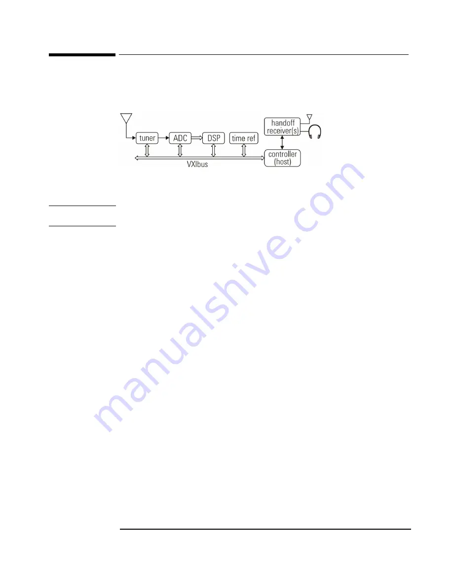
The Block Diagram
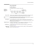
This diagram illustrate how data flows in the system.
Figure 22.
System Block
Diagram
Tuner & ADC
The tuner output is digitized by the ADC and passed to the DSP for search processing. The
system sweeps the spectrum, sending blocks of magnitude data to the controller.
Note
The tuner and ADC blocks are combined into one block when using the HF Receiver input of
the N6830 Dual Channel HF Receiver and 70 MHz IF ADC.
Time Capture
The ADC FIFO buffer may be used to collect time snapshot data. The size of the buffer
depends on the ADC model and the options in it. For example the E1439D ADC has a 1 GB
RAM option that serves the purpose.
Handoff Receivers
As many as 100 handoff receivers can be managed by the E3238S system. These may be
VXI modules (on the VXIbus) or connect via RS232, LAN, GPIB, etc.
Time Reference
An IRIG card may be used to implement accurate time stamping or coordinate signal
processing. See
.
Digital Signal
Processing
This block may represent 1 or as many as 10 E9821A modules. The DSP configuration is
Summary of Contents for E3238S
Page 62: ...62 Hardware Installation ...
Page 94: ...94 Software Installation and Configuration ...
Page 198: ...198 Application Resources ...
Page 218: ...218 Multi Channel Hardware Installation ...
Page 242: ...242 Specifications ...
Page 252: ...252 Appendix A d E3238s Listing E3238S Installation ...
Page 268: ...268 Appendix B d e3238s cfg Listing E3238S Installation ...

