39
Hardware Installation
E1437A, E1438A/B/D, E1439A/B/D, N6830 VXI ADC
ADC modules that use the VXI local bus to transfer data to the DSP module must be installed
in the VXI slot immediately left of the DSP module. ADC modules that use FPDP do not
have this constraint.
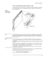
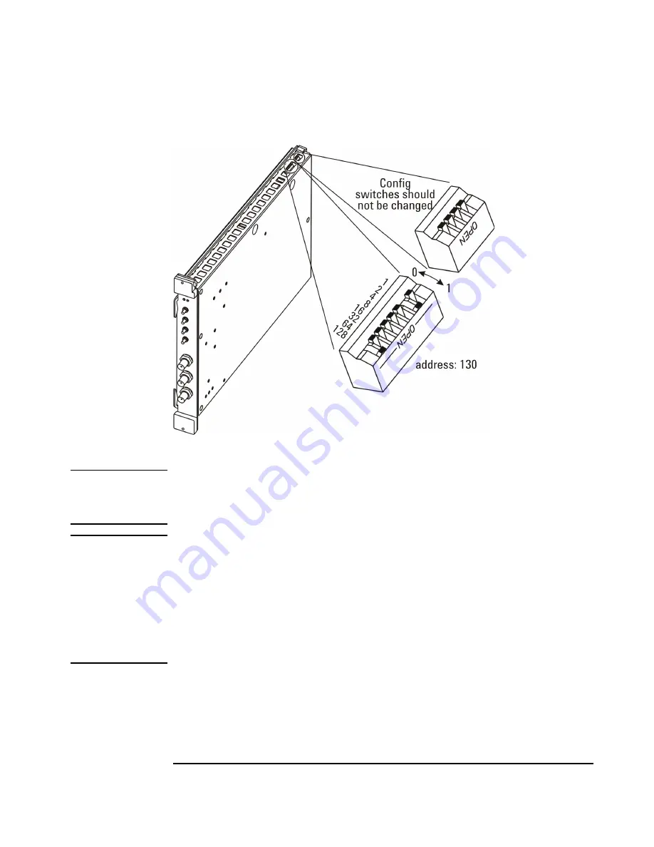
Figure 27.
ADC Logical
Address Setting
.
Note
The N6830 only has an address switch. It does not have a configuration switch. The address
switch sets the N6830 channel one address. The channel two address is the channel one
address plus 1. In the figure above, the channel one address would be 130. The channel two
address would be 131.
Note
The N6830 has a front panel error LED which will blink in the following circumstances:
1. The selected VXI logical address is not valid (0, 254, 255 are invalid). The LED will be lit
continuously.
2. An internal error, such as an unlocked PLL, has occurred. The LED will blink 3 times per
second.
3. An external reference is programmed, but the reference PLL is not locked, or no external
signal is present, or the external reference is low amplitude or has a non-symmetrical duty
cycle. In this case, the LED will blink 1.5 times per second.
4. A framing error from one of the ADC deserializers was detected. In this case, the LED
will blink twice and then pause.
The following information is taken from the d.e3238s.cfg file. Use this information to help
configure the ADC settings in the e3238s.cfg file for your system.
!!!!!!!!!!!!!!!!!!!!!!!!!!!!!!!!!!!!!!!!!!!!!!!!!!!!!!!!!!!!!!!!!!!!!!!!
! Search Receiver ADC Configuration !
!!!!!!!!!!!!!!!!!!!!!!!!!!!!!!!!!!!!!!!!!!!!!!!!!!!!!!!!!!!!!!!!!!!
Summary of Contents for E3238S
Page 62: ...62 Hardware Installation ...
Page 94: ...94 Software Installation and Configuration ...
Page 198: ...198 Application Resources ...
Page 218: ...218 Multi Channel Hardware Installation ...
Page 242: ...242 Specifications ...
Page 252: ...252 Appendix A d E3238s Listing E3238S Installation ...
Page 268: ...268 Appendix B d e3238s cfg Listing E3238S Installation ...

