102
Chapter 2
Block Diagrams
Mnemonics and Connectors
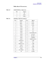
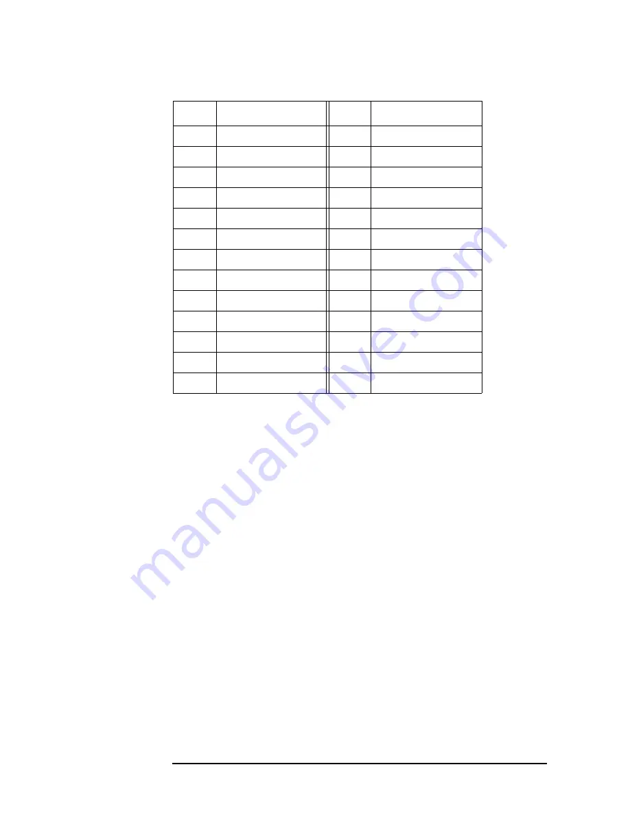
Table 2-8
A21J7 Floppy FFC Cable Connector
Pin
Signal
Pin
Signal
1
FLOPPY_HSL
14
NC
2
DCOM
15
FLOPPY_DIRCL
3
FLOPPY_RDDL
16
NC
4
DCOM
17
FLOPPY_DS3L
5
FLOPPY_WPL
18
FLOPPY_MID
6
DCOM
19
FLOPPY_READY
7
FLOPPY_TR00L
20
NC
8
DCOM
21
FLOPPY_DCHGL
9
FLOPPY_WEL
22
VCC
10
DCOM
23
FLOPPY_DS1L
11
FLOPPY_WDL
24
VCC
12
DCOM
25
FLOPPY_IDXL
13
FLOPPY_STEPL
26
VCC
Summary of Contents for E4406A VSA Series
Page 4: ...4 ...
Page 10: ...10 Contents ...
Page 11: ...11 1 Troubleshooting ...
Page 66: ...66 Chapter1 Troubleshooting How to Return Your Instrument for Service ...
Page 67: ...67 2 Block Diagrams ...
Page 119: ...Chapter 2 119 Block Diagrams Block Diagrams Block Diagrams ...
Page 120: ...120 Chapter2 Block Diagrams Block Diagrams ...
Page 122: ...122 Chapter2 Block Diagrams Block Diagrams ...
Page 124: ...124 Chapter2 Block Diagrams Block Diagrams ...
Page 125: ...125 3 Parts List ...
Page 164: ...164 Chapter3 Parts List Hardware ...
Page 165: ...165 4 Assembly Replacement ...
Page 169: ......
Page 170: ...170 Chapter4 Assembly Replacement Removal and Replacement Procedures ...
Page 227: ...Chapter 4 227 Assembly Replacement Front Frame Subassemblies Figure 4 39 Keypad Parts ...
Page 231: ...231 5 Post Repair Procedures ...
Page 262: ...262 Chapter5 Post Repair Procedures Automated Adjustments ...

