Chapter 3
137
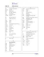
Parts List
Replaceable Parts
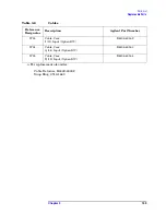
E4406-00077
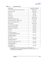
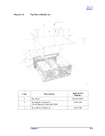
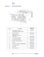
Dress Panel, SCSI
E4406-00017
Trim, Side
5041-9172
Rear Feet
5041-9611
Bottom Feet
5041-9167
Strap Handles
E4400-60026
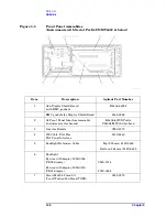
Motherboard Shield Assembly
E4406-60024
Ferrite, W6 Flat Panel Interface Cable
9170-1727
Ferrite, W10 Disk Drive Cable
9170-1726
Shield, Ferrite
E4406-20105
CPU Bottom Plastic Spacers
0380-4163
Memory Plastic Standoffs
0380-4663
Mid Web Fan Plastic Rivet
0361-1272
Nut, W20
2950-0035
Nut, A27
2950-0154
Screw M3x0.5 8mm-LG
(Crest Washer-Pan Head-TORX)
0515-0372
Screw M3x0.5 6mm-LG
(Flat Head - TORX)
0515-1227
Screws, Jack
0380-1858
Screwlock Stand Off-Hex
0.312-IN-LG, SCSI
1252-5828
Screw M4x0.7 25mm-LG, Rear Feet
0515-1619
Washer-LK HLC No. 10
0.194-IN-ID, GPIB
2190-0034
Standoff-HEX
0.327-IN-LG, GPIB
0380-0644
a. For instruments with serial numbers between US3845101 and
US40061423, you must replace the Front Frame Assembly, Chassis, and
Rear Frame Assembly together.
Table 3-5
Mechanical Parts
Description
Agilent Part Number
Summary of Contents for E4406A VSA Series
Page 4: ...4 ...
Page 10: ...10 Contents ...
Page 11: ...11 1 Troubleshooting ...
Page 66: ...66 Chapter1 Troubleshooting How to Return Your Instrument for Service ...
Page 67: ...67 2 Block Diagrams ...
Page 119: ...Chapter 2 119 Block Diagrams Block Diagrams Block Diagrams ...
Page 120: ...120 Chapter2 Block Diagrams Block Diagrams ...
Page 122: ...122 Chapter2 Block Diagrams Block Diagrams ...
Page 124: ...124 Chapter2 Block Diagrams Block Diagrams ...
Page 125: ...125 3 Parts List ...
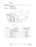
Page 164: ...164 Chapter3 Parts List Hardware ...
Page 165: ...165 4 Assembly Replacement ...
Page 169: ......
Page 170: ...170 Chapter4 Assembly Replacement Removal and Replacement Procedures ...
Page 227: ...Chapter 4 227 Assembly Replacement Front Frame Subassemblies Figure 4 39 Keypad Parts ...
Page 231: ...231 5 Post Repair Procedures ...
Page 262: ...262 Chapter5 Post Repair Procedures Automated Adjustments ...


