168
Chapter 4
Assembly Replacement
Removal and Replacement Procedures
Removal and Replacement Procedures
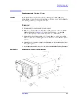
"Instrument Outer Case" on page 171
"A4 Disk Drive and A5 Disk Drive Board" on page 177
"A7 Baseband I/Q Assembly (Option B7C)" on page 182
"A10 Digital IF and A12 Analog IF Assemblies" on page 185
"A14 Fan Control Board" on page 187
"A15 Daughter Board" on page 189
"A17 RF, A18 Reference, and A19 Synthesizer Assemblies" on page
191
"A22 Processor Assembly" on page 202
“A22A1 DRAM, A22A2 Flash, and A22A3 GP-IB Capacitor Boards”
on page 205
“A27 Rear Panel Connector Board” on page 208
"Center Web Cables W9, W11, and W12" on page 212
Summary of Contents for E4406A VSA Series
Page 4: ...4 ...
Page 10: ...10 Contents ...
Page 11: ...11 1 Troubleshooting ...
Page 66: ...66 Chapter1 Troubleshooting How to Return Your Instrument for Service ...
Page 67: ...67 2 Block Diagrams ...
Page 119: ...Chapter 2 119 Block Diagrams Block Diagrams Block Diagrams ...
Page 120: ...120 Chapter2 Block Diagrams Block Diagrams ...
Page 122: ...122 Chapter2 Block Diagrams Block Diagrams ...
Page 124: ...124 Chapter2 Block Diagrams Block Diagrams ...
Page 125: ...125 3 Parts List ...
Page 164: ...164 Chapter3 Parts List Hardware ...
Page 165: ...165 4 Assembly Replacement ...
Page 169: ......
Page 170: ...170 Chapter4 Assembly Replacement Removal and Replacement Procedures ...
Page 227: ...Chapter 4 227 Assembly Replacement Front Frame Subassemblies Figure 4 39 Keypad Parts ...
Page 231: ...231 5 Post Repair Procedures ...
Page 262: ...262 Chapter5 Post Repair Procedures Automated Adjustments ...

