Chapter 1
19
Troubleshooting
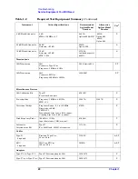
Service Equipment You Will Need
Counters
Universal Counter
Frequency: 10 MHz
Gate time: 10 to 100 seconds
Must be capable of measuring signal
at +7dBm (0.5V rms)
53132A
P, T
Meters
Digital Multimeter
3458A
A, T
Power Meter
Dual Channel
Absolute Accuracy:
±
0.5%
Power Reference Accuracy:
±
0.9%
E4419A
E4419B
A, P
Power Sensor
Frequency Range: 1 MHz to 4.0 GHz.
SWR:
50 MHz:
≤
1.05
1 MHz to 4 GHz SWR:
≤
1.22
Connector: Type-N (m), 50
Ω
Cal Factor: Characterized by
standards lab to:
±
0.6%
8482A
Option H84
8482A STD
Note: The use of
this model will
increase
measurement
uncertainty
A, P
Power Sensor
Frequency Range: 1 MHz to 4 GHz.
SWR:
50 MHz:
≤
1.10
1 MHz to 4 GHz:
≤
1.30
8482A
P
Power Sensor
High sensitivity: Used to measure
−
25 dBm
signal at 50 MHz only (requires a 30 dB pad)
8481D
A
Oscilloscope
Digitizing Oscilloscope
150 MHz
54602B
54820A
T
Standards
Frequency Standard
Frequency: 10 MHz
Accuracy: <
±
1 X10
−
10
5071A
A, P
Attenuators
10 dB Step Attenuator
Range: 0 to 110 dB
Accuracy: Characterized by
standards lab to:
±
0.005 + 0.0052/10 dB step
Calibrated at 50 MHz
SWR at 50 MHz:
≤
1.2
8496G P
1 dB Step Attenuator
Range: 0 to 11 dB
Accuracy: Characterized by
standards lab to:
±
0.01 dB
Calibrated at 50 MHz
SWR at 50 MHz:
≤
1.2
8494G P
Attenuator Driver
Compatible with the 8496G and 8494G step
attenuators.
11713A
P
Table 1-2
Required Test Equipment Summary
(Continued)
Instrument
Critical Specifications
Recommended
Agilent Model
Number
Alternative
Agilent Model
Number
Use
a
Summary of Contents for E4406A VSA Series
Page 4: ...4 ...
Page 10: ...10 Contents ...
Page 11: ...11 1 Troubleshooting ...
Page 66: ...66 Chapter1 Troubleshooting How to Return Your Instrument for Service ...
Page 67: ...67 2 Block Diagrams ...
Page 119: ...Chapter 2 119 Block Diagrams Block Diagrams Block Diagrams ...
Page 120: ...120 Chapter2 Block Diagrams Block Diagrams ...
Page 122: ...122 Chapter2 Block Diagrams Block Diagrams ...
Page 124: ...124 Chapter2 Block Diagrams Block Diagrams ...
Page 125: ...125 3 Parts List ...
Page 164: ...164 Chapter3 Parts List Hardware ...
Page 165: ...165 4 Assembly Replacement ...
Page 169: ......
Page 170: ...170 Chapter4 Assembly Replacement Removal and Replacement Procedures ...
Page 227: ...Chapter 4 227 Assembly Replacement Front Frame Subassemblies Figure 4 39 Keypad Parts ...
Page 231: ...231 5 Post Repair Procedures ...
Page 262: ...262 Chapter5 Post Repair Procedures Automated Adjustments ...

