20
Chapter 1
Troubleshooting
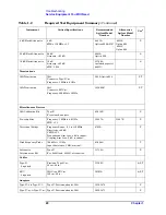
Service Equipment You Will Need
6 dB Fixed Attenuator
6 dB
SWR at 50 MHz:
≤
1.1
8491A
Options 006 & H47
8491B
Option 006
8491C
Option 006
P
20 dB Fixed Attenuator
20 dB
Accuracy:
+
0.5 dB
8491A
Option 020
A
30 dB Fixed Attenuator
30 dB
Accuracy:
±
.05 dB
SWR: 1.05:1
11708A
(included as part of
8481D)
A
Terminations
50
Ω
Termination
50
Ω
Connector: Type-N (m)
Frequency: 1 MHz to 4 GHz
909A Option 012
P, T
50
Ω
Termination
50
Ω
Connector: BNC (m)
Frequency: 100 kHz to 5 MHz
1250-0207
P, T
Miscellaneous Devices
50
Ω
Calibration Kit
Type-N
For network analyzer
85032B
P
Power Splitter
Frequency: 1 MHz to 4.0 GHz
SWR:
≤
1.1
11667A
11667B
P
Directional Bridge
Frequency Range: 0.1 to 110 MHz
Directivity: >40 dB
VSWR:
≤
1.1
Transmission Arm Loss: 6 dB (nominal)
Coupling Arm Loss: 6 dB (nominal)
8721A
P
High Frequency Probe
300 kHz to 3 GHz
Input Resistance: 1 M
Ω
(nominal)
85024A
T
Attenuator
Interconnector Kit
Type-N
For 8496G and 8494G attenuators.
11716A
P
Cables
Type-N
2 required
Precision Type-N (m)
62 cm (24 in.)
11500C
A, P, T
BNC
2 required
50
Ω
Coax BNC (m)
120 cm (48 in.)
10503A
A, P, T
Adapters
Type-N (f) to Type-N (f)
Type-N, Precision adaptor, 50
Ω
1250-1472
P
Type-N (m) to Type-N (m) Type-N, Precision adaptor, 50
Ω
1250-1475
P
Table 1-2
Required Test Equipment Summary
(Continued)
Instrument
Critical Specifications
Recommended
Agilent Model
Number
Alternative
Agilent Model
Number
Use
a
Summary of Contents for E4406A VSA Series
Page 4: ...4 ...
Page 10: ...10 Contents ...
Page 11: ...11 1 Troubleshooting ...
Page 66: ...66 Chapter1 Troubleshooting How to Return Your Instrument for Service ...
Page 67: ...67 2 Block Diagrams ...
Page 119: ...Chapter 2 119 Block Diagrams Block Diagrams Block Diagrams ...
Page 120: ...120 Chapter2 Block Diagrams Block Diagrams ...
Page 122: ...122 Chapter2 Block Diagrams Block Diagrams ...
Page 124: ...124 Chapter2 Block Diagrams Block Diagrams ...
Page 125: ...125 3 Parts List ...
Page 164: ...164 Chapter3 Parts List Hardware ...
Page 165: ...165 4 Assembly Replacement ...
Page 169: ......
Page 170: ...170 Chapter4 Assembly Replacement Removal and Replacement Procedures ...
Page 227: ...Chapter 4 227 Assembly Replacement Front Frame Subassemblies Figure 4 39 Keypad Parts ...
Page 231: ...231 5 Post Repair Procedures ...
Page 262: ...262 Chapter5 Post Repair Procedures Automated Adjustments ...

