Chapter 1
23
Troubleshooting
Check the Basics
Check the Basics
A problem can often be solved by repeating the procedure you were
following when the problem occurred. Before calling Agilent
Technologies or returning the instrument for service, please make the
following checks:
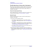
1. Is there power at the receptacle?
2. Is the instrument turned on? Check to see if the front panel LED is
green. This indicates the power supply is on.
3. If other equipment, cables, and connectors are being used with the
instrument, make sure they are connected properly and operating
correctly.
4. Review the procedure for the measurement being performed when
the problem appeared. Are all the settings correct?
5. If the instrument is not functioning as expected, return the unit to a
known state by pressing the
Preset
key.
6. Is the measurement being performed, and the results that are
expected, within the specifications and capabilities of the
instrument? Refer to the specifications book for instrument
specifications.
7. In order to meet specifications, the instrument must be aligned.
Press
System
,
Alignments
,
Align All Now
. The diagnostic tests should
all pass. If the instrument displays a failure during these tests, refer
to
.
8. Check to see if the instrument has the latest firmware before
starting the troubleshooting procedure. Press
System
,
More
,
Show
System
. The firmware revision is listed under
Firmware Rev
. Go to
the web site http://www.agilent.com/find/vsa to check for the latest
revision and download new firmware if necessary. Refer to
“Updating Firmware” on page 63
.
9. Is the instrument displaying an error message? If so, refer to the
Agilent Technologies E4406A VSA Instrument Messages and
Functional Tests
manual.
10. If the necessary test equipment is available, perform the functional
checks in the user’s guide for your instrument.
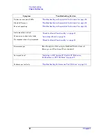
11. Determine which troubleshooting section to start with by comparing
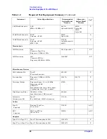
the instrument’s symptoms to the symptoms in the following table.
Summary of Contents for E4406A VSA Series
Page 4: ...4 ...
Page 10: ...10 Contents ...
Page 11: ...11 1 Troubleshooting ...
Page 66: ...66 Chapter1 Troubleshooting How to Return Your Instrument for Service ...
Page 67: ...67 2 Block Diagrams ...
Page 119: ...Chapter 2 119 Block Diagrams Block Diagrams Block Diagrams ...
Page 120: ...120 Chapter2 Block Diagrams Block Diagrams ...
Page 122: ...122 Chapter2 Block Diagrams Block Diagrams ...
Page 124: ...124 Chapter2 Block Diagrams Block Diagrams ...
Page 125: ...125 3 Parts List ...
Page 164: ...164 Chapter3 Parts List Hardware ...
Page 165: ...165 4 Assembly Replacement ...
Page 169: ......
Page 170: ...170 Chapter4 Assembly Replacement Removal and Replacement Procedures ...
Page 227: ...Chapter 4 227 Assembly Replacement Front Frame Subassemblies Figure 4 39 Keypad Parts ...
Page 231: ...231 5 Post Repair Procedures ...
Page 262: ...262 Chapter5 Post Repair Procedures Automated Adjustments ...


