236
Chapter 5
Post-Repair Procedures
Post-Repair Procedures
Test equipment you will need
Refer to
, for a list of recommended equipment and
critical test equipment specifications for the performance verification
and adjustments.
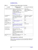
A18 Reference Assembly
Perform in the order listed.
“Internal
10 MHz Frequency Reference
Adjustment”, “Internal 50 MHz
Calibrator Adjustment”,
(Use N7812A software or the manual
procedures on
and
.),
“Phase Noise”,
“Spurious Responses”,
“Internal 10 MHz Frequency
Reference”
A19 Synthesizer
Assembly
Perform in the order listed.
“Synthesizer Adjustment Number
Two”, “Synthesizer Adjustment
Number One”
“Phase Noise”, “Spurious
Responses”, “Residual
FM”
A21 MotherBoard
None
None
A22 CPU (processor)
Assembly
“Configuring a Replacement CPU
Assembly” on page 241
None
A22A1 DRAM Card
None
None
A22A2 Flash Memory
Board
“Configuring a Replacement Flash
Memory Assembly” on page 244
,
“Synthesizer Adjustment Number
Two”
“Phase Noise”
A25 SCSI Board
“External Keyboard Test” on page 239
None
A27 Rear Panel
Connector Board
Check for presence of the
10 MHz OUT on the rear panel
connector.
Check the external reference mode
operation by connecting an external
reference input signal and verifying
performance.
None
A3A1, A3A2 Inverter
Boards
Ensure that the display quality and
brightness are satisfactory.
None
Table 5-1
Post-Repair Testing Requirements (Continued)
Assembly
Adjustments, Tests, &
Configuration
Performance Verification
Summary of Contents for E4406A VSA Series
Page 4: ...4 ...
Page 10: ...10 Contents ...
Page 11: ...11 1 Troubleshooting ...
Page 66: ...66 Chapter1 Troubleshooting How to Return Your Instrument for Service ...
Page 67: ...67 2 Block Diagrams ...
Page 119: ...Chapter 2 119 Block Diagrams Block Diagrams Block Diagrams ...
Page 120: ...120 Chapter2 Block Diagrams Block Diagrams ...
Page 122: ...122 Chapter2 Block Diagrams Block Diagrams ...
Page 124: ...124 Chapter2 Block Diagrams Block Diagrams ...
Page 125: ...125 3 Parts List ...
Page 164: ...164 Chapter3 Parts List Hardware ...
Page 165: ...165 4 Assembly Replacement ...
Page 169: ......
Page 170: ...170 Chapter4 Assembly Replacement Removal and Replacement Procedures ...
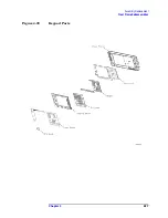
Page 227: ...Chapter 4 227 Assembly Replacement Front Frame Subassemblies Figure 4 39 Keypad Parts ...
Page 231: ...231 5 Post Repair Procedures ...
Page 262: ...262 Chapter5 Post Repair Procedures Automated Adjustments ...

