264
Index
Index
A19 synthesizer assembly
,
A2 flat panel display
A21 fan control board
,
A22 processor assembly
A24 SCSI board
,
A3 front panel interface board
,
A4 disk drive
,
A6 power supply assembly
attenuator steps
,
auto align tests, description
,
auto alignment routine
auto boot
,
B
backlight
removal
,
bandpass filter description
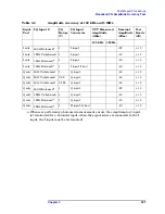
base band I/Q amplitude accuracy
test description
,
basic functionality,
troubleshooting
basics, troubleshooting
,
battery
bezel, removal
,
Block Diagrams
,
boot process
,
burp mode
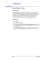
burst trigger
test description
,
bypass mode
C
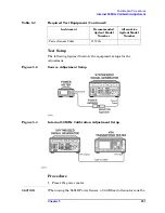
calibrator adjustment
test description
,
calibrator oscillator description
,
calibrator switch description
Choose Option key
,
clock generator description
configuration information
configure a replacement CPU
configuring I/O
connector mnemonics
contacting Agilent Technologies
,
CPU assembly
configuring
CPU assembly, see A22 processor
critical data
D
daughter board, see A15 daughter
dead instrument,
troubleshooting
,
diagnostic check
,
digital signal processing block
,
disk drive, see A4 disk drive
display
display filter
removal
down conversion
,
DRAM
see A22A1 DRAM board
DRAM board
E
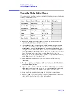
editing text
electrostatic discharge
entering
host name
,
IP address
serial number
entering configuration
information
,
equipment
adjustments
performance verification tests
,
ESD Information
,
Ethernet Addr key
external keyboard
test description
external monitor
external trigger
front panel connector removal
,
F
fan control board, see A14 fan
fan voltages
,
fans
removal
fans, troubleshooting
firmware updating
,
first doubler description
,
first LO
,
first mixer description
,
Flash
,
see A22A2 Flash board
,
flash memory board
,
replacement
flat panel display
part number
frequency reference adjustment
test description
,
front panel interface board, see A3
Front Panel Test
front panel, see A1 front frame
fuse
,
G
gain range select description
GPIB Address key
,
GP-IB capacitor board
see A22A3 GP-IB capacitor
board
H
Host Name key
how to order parts
,
how to return your analyzer for
service
,
HSYNC, troubleshooting
I
I/O
configuring
I/Q input circuitry
IF gain curve
IF image filter
,
image filter description
inoperative instrument,
troubleshooting
inoperative spectrum analyzer
input attenuator description
input selector switch description
,
Install Now key
,
installing measurement
personalities
,
instrument packaging
,
instrument serial number
,
internal 10 MHz frequency
reference adjustment
test description
,
internal 50 MHz calibrator
adjustment
test description
,
internal calibrator adjustment
test description
,
internal frequency reference
adjustment
test description
,
inverter boards
Summary of Contents for E4406A VSA Series
Page 4: ...4 ...
Page 10: ...10 Contents ...
Page 11: ...11 1 Troubleshooting ...
Page 66: ...66 Chapter1 Troubleshooting How to Return Your Instrument for Service ...
Page 67: ...67 2 Block Diagrams ...
Page 119: ...Chapter 2 119 Block Diagrams Block Diagrams Block Diagrams ...
Page 120: ...120 Chapter2 Block Diagrams Block Diagrams ...
Page 122: ...122 Chapter2 Block Diagrams Block Diagrams ...
Page 124: ...124 Chapter2 Block Diagrams Block Diagrams ...
Page 125: ...125 3 Parts List ...
Page 164: ...164 Chapter3 Parts List Hardware ...
Page 165: ...165 4 Assembly Replacement ...
Page 169: ......
Page 170: ...170 Chapter4 Assembly Replacement Removal and Replacement Procedures ...
Page 227: ...Chapter 4 227 Assembly Replacement Front Frame Subassemblies Figure 4 39 Keypad Parts ...
Page 231: ...231 5 Post Repair Procedures ...
Page 262: ...262 Chapter5 Post Repair Procedures Automated Adjustments ...


