46
Chapter 1
Troubleshooting
Isolating an RF, Analog IF, Digital IF, Reference, Synthesizer, or CPU Problem
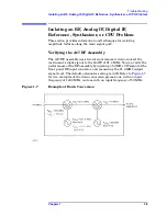
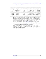
Figure 1-9
E4406-60015 Extender Measurement Locations
Measurement
Location
Signal Description
Test Equipment Used
Expected
Level
A
power supply
DVM
+5.2 VDC
B
power supply
DVM
−
5.2 VDC
C
power supply
DVM
+15 VDC
D
power supply
DVM
−
15 VDC
E
power supply
DVM
+9 VDC
F
power supply
DVM
+32 VDC
G
Gate Arm
DVM
+3.7 VDC
H
Gate Trig
DVM
+3.7 VDC
I
Sweep Arm
DVM
+3.7 VDC
J
Sweep Trig
DVM
+3.7 VDC
Summary of Contents for E4406A VSA Series
Page 4: ...4 ...
Page 10: ...10 Contents ...
Page 11: ...11 1 Troubleshooting ...
Page 66: ...66 Chapter1 Troubleshooting How to Return Your Instrument for Service ...
Page 67: ...67 2 Block Diagrams ...
Page 119: ...Chapter 2 119 Block Diagrams Block Diagrams Block Diagrams ...
Page 120: ...120 Chapter2 Block Diagrams Block Diagrams ...
Page 122: ...122 Chapter2 Block Diagrams Block Diagrams ...
Page 124: ...124 Chapter2 Block Diagrams Block Diagrams ...
Page 125: ...125 3 Parts List ...
Page 164: ...164 Chapter3 Parts List Hardware ...
Page 165: ...165 4 Assembly Replacement ...
Page 169: ......
Page 170: ...170 Chapter4 Assembly Replacement Removal and Replacement Procedures ...
Page 227: ...Chapter 4 227 Assembly Replacement Front Frame Subassemblies Figure 4 39 Keypad Parts ...
Page 231: ...231 5 Post Repair Procedures ...
Page 262: ...262 Chapter5 Post Repair Procedures Automated Adjustments ...


