Chapter 1
65
Troubleshooting
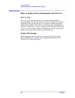
How to Return Your Instrument for Service
Other Packaging
CAUTION
Instrument damage can result from using packaging materials other
than those specified. Never use styrene pellets in any shape as
packaging materials. They do not adequately cushion the equipment or
prevent it from shifting in the carton. They cause equipment damage by
generating static electricity and by lodging in the instrument louvers,
blocking airflow.
You can repackage the instrument with commercially available
materials, as follows:
1. Attach a completed service tag to the instrument.
2. If you have a front-panel cover, install it on the instrument; if not,
protect the control panel with cardboard.
3. Wrap the instrument in antistatic plastic to reduce the possibility of
damage caused by electrostatic discharge.
4. Use a strong shipping container. A double-walled, corrugated
cardboard carton with 159 kg (350 lb) bursting strength is adequate.
The carton must be both large enough and strong enough to
accommodate the instrument. Allow at least 3 to 4 inches on all sides
of the instrument for packing material.
5. Surround the equipment with three to four inches of packing
material and prevent the equipment from moving in the carton. If
packing foam is not available, the best alternative is S.D.-240 Air
Cap™ from Sealed Air Corporation (Hayward, California, 94545).
Air Cap looks like a plastic sheet filled with 1-1/4 inch air bubbles.
Use the pink-colored Air Cap to reduce static electricity. Wrapping
the equipment several times in this material should both protect the
equipment and prevent it from moving in the carton.
6. Seal the shipping container securely with strong nylon adhesive
tape.
7. Mark the shipping container “FRAGILE, HANDLE WITH CARE” to
assure careful handling.
8. Retain copies of all shipping papers.
Summary of Contents for E4406A VSA Series
Page 4: ...4 ...
Page 10: ...10 Contents ...
Page 11: ...11 1 Troubleshooting ...
Page 66: ...66 Chapter1 Troubleshooting How to Return Your Instrument for Service ...
Page 67: ...67 2 Block Diagrams ...
Page 119: ...Chapter 2 119 Block Diagrams Block Diagrams Block Diagrams ...
Page 120: ...120 Chapter2 Block Diagrams Block Diagrams ...
Page 122: ...122 Chapter2 Block Diagrams Block Diagrams ...
Page 124: ...124 Chapter2 Block Diagrams Block Diagrams ...
Page 125: ...125 3 Parts List ...
Page 164: ...164 Chapter3 Parts List Hardware ...
Page 165: ...165 4 Assembly Replacement ...
Page 169: ......
Page 170: ...170 Chapter4 Assembly Replacement Removal and Replacement Procedures ...
Page 227: ...Chapter 4 227 Assembly Replacement Front Frame Subassemblies Figure 4 39 Keypad Parts ...
Page 231: ...231 5 Post Repair Procedures ...
Page 262: ...262 Chapter5 Post Repair Procedures Automated Adjustments ...


