90
Chapter 2
Block Diagrams
Mnemonics and Connectors
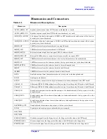
MIS0
Motherboard serial bus master in slave out data signal from all vertical boards to the digital IF
board
MOSI
Motherboard serial bus master out slave in data signal from the digital IF board to all vertical
boards
N12
−
12 V power supply from the motherboard to the CPU board
N15
−
15 V power supply on the motherboard
N5.2
−
5.2 V power supply on the motherboard
N6
−
6 V power supply from the fan control board to the synthesizer board
NC
No connect
OPT_TRIG1
Option trigger signal #1 output from the 4 motherboard option slots to the analog IF board
OPT_TRIG2
Option trigger signal #2 output from the 4 motherboard option slots to the analog IF board
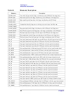
P12
+12 V power supply from the motherboard to the CPU board
P15
+15 V power supply on the motherboard
P15SBY
+15 V standby power supply on the motherboard
P32
+32 V power supply on the motherboard
P5.2
+5.2 V power supply on the motherboard
ID0
Motherboard option board slot ID bit 0
ID1
Motherboard option board slot ID bit 1
P9
+9 V power supply on the motherboard
PCMCIA_AD0
not used
PCMCIA_AD1
not used
PCMCIA_AD2
not used
PCMCIA_CLK7
not used
PCMCIA_CS1L
not used
PCMCIA_CS2L
not used
PCMCIA_D0 to D7
not used
PCMCIA_INTRL
not used
PCMCIA_LTCHENL
not used
PCMCIA_OEL
not used
PCMCIA_RSTL
not used
PCMCIA_WEL
not used
POWFAILL
PRE_LEVEL_DRIVE
LO leveling loop feedback signal from the RF board to the synthesizer board
PROBE_N12.6
Probe power
−
12.6 V power supply from the fan control board to the front panel interface board
Table 2-1
Mnemonic Descriptions
Mnemonic
Description
Summary of Contents for E4406A VSA Series
Page 4: ...4 ...
Page 10: ...10 Contents ...
Page 11: ...11 1 Troubleshooting ...
Page 66: ...66 Chapter1 Troubleshooting How to Return Your Instrument for Service ...
Page 67: ...67 2 Block Diagrams ...
Page 119: ...Chapter 2 119 Block Diagrams Block Diagrams Block Diagrams ...
Page 120: ...120 Chapter2 Block Diagrams Block Diagrams ...
Page 122: ...122 Chapter2 Block Diagrams Block Diagrams ...
Page 124: ...124 Chapter2 Block Diagrams Block Diagrams ...
Page 125: ...125 3 Parts List ...
Page 164: ...164 Chapter3 Parts List Hardware ...
Page 165: ...165 4 Assembly Replacement ...
Page 169: ......
Page 170: ...170 Chapter4 Assembly Replacement Removal and Replacement Procedures ...
Page 227: ...Chapter 4 227 Assembly Replacement Front Frame Subassemblies Figure 4 39 Keypad Parts ...
Page 231: ...231 5 Post Repair Procedures ...
Page 262: ...262 Chapter5 Post Repair Procedures Automated Adjustments ...


