background image

232

Chapter 5

Language Reference

INSTrument Subsystem

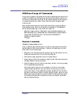
Select Application

:INSTrument[:SELect]

BASIC|SERVICE|CDMA|CDMA2K|GSM|EDGEGSM|IDEN|NADC|PDC|

WCDMA|ARIBWCDMA

:INSTrument[:SELect]?

Select the measurement application (mode). The actual available
choices depends upon which applications are installed in the
instrument. A list of the valid choices can be seen on the display by
pressing

System, Show System

 and looking at the

Name

 column.

Once the instrument mode is selected, only the commands that are
valid for that mode can be executed. SYSTem:HELP:HEADers? can be
used provide a list of the valid commands.

Basic mode - Makes basic receiver measurements

Service mode - Used only for servicing the instrument

CDMA mode - Makes cdmaOne (code division multiple access)
standard measurements

CDMA2K mode - Makes cdma2000 (wide-band code division
multiple access) standard measurements

EDGEGSM mode - Makes GSM (global system for mobile
communications) and EDGE (enhanced data rates for global
evolution) standard measurements

GSM mode - Makes GSM (global system for mobile communications)
standard measurements

IDEN mode - Makes iDEN (integrated digital enhanced network)
standard measurements

NADC mode - Makes NADC (North American Digital Cellular)
standard measurements

PDC mode - Makes PDC (Personal Digital Cellular) standard
measurements

WCDMA mode - Makes W-CDMA (wide-band CDMA) measurements
for the 3GPP (third generation partnership project) standards

ARIBWCDMA mode - Makes W-CDMA (wide-band CDMA)
measurements for the trial 98 and ARIB standards

Factory Preset
and *RST:

Persistent state with factory default of the first
installed application other than the service mode.

Front Panel
Access:

Mode

Summary of Contents for E4406A VSA Series

Page 1: ...Programmer s Guide Agilent Technologies E4406A VSA Series Transmitter Tester Manufacturing Part Number E4406 90146 Printed in USA July 2000 Copyright 1999 2000 Agilent Technologies Inc ...

Page 2: ...te until the indicated conditions are fully understood and met CAUTION Caution denotes a hazard It calls attention to a procedure that if not correctly performed or adhered to could result in damage to or destruction of the instrument Do not proceed beyond a caution sign until the indicated conditions are fully understood and met WARNING This is a Safety Class 1 Product provided with a protective ...

Page 3: ...or use with an instrument will execute its programming instructions when properly installed on that instrument Agilent Technologies does not warrant that the operation of the instrument or software or firmware will be uninterrupted or error free LIMITATION OF WARRANTY The foregoing warranty shall not apply to defects resulting from improper or inadequate maintenance by Buyer Buyer supplied softwar...

Page 4: ...4 ...

Page 5: ...ords and Syntax 62 Special Characters in Commands 63 Parameters in Commands 64 Putting Multiple Commands on the Same Line 67 Using the Instrument Status Registers 69 What are the Status Registers 70 Why Would You Use the Status Registers 72 Using a Status Register 74 Using the Service Request SRQ Method 74 Overall Status Register System 76 Status Byte Register 77 Standard Event Status Register 80 ...

Page 6: ...Binary Trace Data in an ASCII File 130 Example 131 Saving ASCII Trace Data in an ASCII File 133 Example 134 Saving and Recalling Instrument State Data 136 Example 137 Performing Alignments and Getting Pass Fail Results 139 Example 139 Using C Programming Over Socket LAN 141 Example 141 Using C Programming Over Socket LAN Windows NT 155 Example 156 Using Java Programming Over Socket LAN 158 Example...

Page 7: ...enter Frequency 198 Align the ADC Offset 199 Align the ADC RAM Gain 199 Align All Instrument Assemblies 199 Calibrate the Attenuator 200 Automatic Alignment 200 Calibration Comb Alignment 201 Calibration Display Detail 201 Align the IF Flatness 201 Auto Adjust the Internal 10 MHz Frequency Reference 202 Align the ADC 202 Align the IF Gain 202 Calibrate the Nominal System Gain 203 Align the IF 203 ...

Page 8: ... Subsystem 222 Screen Printout Destination 222 Custom Printer Color Capability 222 Custom Printer Language 223 Printer Type 223 Color Hard Copy 224 Print a Hard Copy 224 Form Feed the Print Item 224 Page Orientation 225 Number of Items Printed on a Page 225 Reprint the Last Image 226 Screen Dump Query 226 Screen Dump Image Inverting 227 Screen Dump Now 227 INITiate Subsystem 228 Continuous or Sing...

Page 9: ...Number 290 Select the Lowest ARFCN 291 Select the Middle ARFCN 292 Select the Highest ARFCN 293 Burst Type 293 Channel Burst Type 294 Digital Demod PN Offset 294 RF Channel Number 295 Time Slot number 296 Time Slot Auto 297 Training Sequence Code TSC 297 Training Sequence Code TSC Auto 298 Channel Power Measurement 299 Correction for Base Station RF Port External Attenuation 304 Correction for BTS...

Page 10: ... Read and Write Calibration Data 347 Prepare Calibration Files for Access 347 Load Default Calibration Data to NRAM 347 Unlock Calibration Files 348 Set Default Calibration Data 348 Store Calibration Data in EEROM 348 STATus Subsystem 349 Operation Register 349 Preset the Status Byte 351 Questionable Register 351 Questionable Calibration Register 353 Questionable Frequency Register 354 Questionabl...

Page 11: ...me Trigger Sync Mode 374 Frame Trigger Synchronization Offset 375 Trigger Holdoff 375 Video IF Trigger Delay 376 Video IF Trigger Level 376 Video IF Trigger Slope 377 RF Burst Trigger Delay 377 RF Burst Trigger Level 378 RF Burst Trigger Slope 378 6 Error Messages Error Queues 380 Front Panel Error Messages 380 SCPI Remote Interface Error Messages 383 Clearing the Error Queue 384 No Error 384 Erro...

Page 12: ... cdmaOne Specific Error Messages 200 to 299 408 NADC Specific Error Messages 300 to 399 409 PDC Specific Error Messages 400 to 499 410 W CDMA Specific Error Messages 500 to 599 411 cdma2000 Specific Error Messages 600 to 699 411 ...

Page 13: ...umber 79 number 79 SRE 192 79 SRE 79 SRE number 79 OPC 81 ESR 82 ESE number 82 number 82 ESE 192 82 ESE 82 ESE number 82 visa h 84 ViSession 84 ViSession 84 ViSession 84 viOpenDefaultRM 84 viOpenDefaultRM 84 viOpen 84 viPrintf 85 viScanf 85 viPrintf 85 RST 85 viPrintf 85 ...

Page 14: ...M 88 ViSession 88 ViSession 88 visatype h 88 ViSession 88 viOpenDefaultRM 89 viOpenDefaultRM 89 viOpenDefaultRM 89 viOpenDefaultRM 89 viOpenDefaultRM 89 viOpen 89 viOpenDefaultRM 89 viOpenDefaultRM 90 viOpen 90 viOpen 90 viOpen 90 viOpen 90 viOpenDefaultRM 90 viOpen 91 viClose 92 viFindRsrc 92 viWaitOnEvent 92 viClose 92 ...

Page 15: ... 0 1 178 CALCulate ACP LIMit STATe 178 CALCulate ACP LIMit TEST OFF ON 0 1 178 CALCulate ACP LIMit TEST 178 CALCulate CLIMits FAIL 178 CALCulate DATA n 179 CALCulate DATA n COMPress BLOCk CFIT MAXimum MEAN MINimum RMS SAM Ple SDEViation soffset length roffset 179 CALCulate DATA n PEAKs threshold excursion AMPLitude FREQuency TIME 183 CALCulate measurement MARKer AOFF 188 CALCulate measurement MARK...

Page 16: ...nt MARKer 1 2 3 4 TRACe 191 CALCulate measurement MARKer 1 2 3 4 X param 195 CALCulate measurement MARKer 1 2 3 4 X 195 CALCulate measurement MARKer 1 2 3 4 X POSition integer 196 CALCulate measurement MARKer 1 2 3 4 X POSition 196 CALCulate measurement MARKer 1 2 3 4 Y 196 CALCulate PSTatistic STORe REFerence ON 197 CALibration ABORt 198 CALibration ADC ARANge 198 CALibration ADC ARANge 198 CALib...

Page 17: ...m 203 CALibration GAIN CSYStem 203 CALibration GIF 203 CALibration GIF 203 CALibration GRF 203 CALibration GRF 203 CALibration IMAGefilter 203 CALibration IMAGefilter 203 CALibration LOAD DEFault 204 CALibration PFILter LCWide 204 CALibration PFILter LCWide 204 CALibration PFILter LCNarrow 204 CALibration PFILter LCNarrow 204 CALibration PFILter XTALWide 204 CALibration PFILter XTALWide 204 CALibr...

Page 18: ...9 CONFigure measurement 210 CONFigure 210 DISPlay ACP VIEW BGRaph SPECtrum 211 DISPlay ACP VIEW 211 DISPlay ANNotation TITLe DATA string 211 DISPlay ANNotation TITLe DATA 211 DISPlay ANNotation TITLe STATe OFF ON 0 1 212 DISPlay ANNotation TITLe STATe 212 DISPlay ENABle OFF ON 0 1 212 DISPlay ENABle 212 DISPlay EVM VIEW POLar CONStln QUAD 212 DISPlay EVM VIEW 212 DISPlay FORMat TILE 213 DISPlay FO...

Page 19: ...Vice LANGuage PCL3 PCL5 223 HCOPy DEVice LANGuage 223 HCOPy DEVice TYPE CUSTom NONE 223 HCOPy DEVice TYPE 223 HCOPy IMAGe COLor STATe OFF ON 0 1 224 HCOPy IMAGe COLor STATe 224 HCOPy IMMediate 224 HCOPy ITEM FFEed IMMediate 224 HCOPy PAGE ORIentation LANDscape PORTrait 225 HCOPy PAGE ORIentation 225 HCOPy PAGE PRINts 1 2 225 HCOPy PAGE PRINts 225 HCOPy REPRint IMMediate 226 HCOPy SDUMp DATA GIF BM...

Page 20: ...2 MEASure measurement n 233 CONFigure measurement 234 FETCh measurement n 235 READ measurement n 235 CONFigure ACP 236 FETCh ACP n 236 READ ACP n 236 MEASure ACP n 236 CONFigure AREFerence 244 FETCh AREFerence n 244 READ AREFerence n 244 MEASure AREFerence n 244 CONFigure CHPower 245 FETCh CHPower n 245 READ CHPower n 245 MEASure CHPower n 245 CONFigure PSTatistic 246 FETCh PSTatistic n 246 READ P...

Page 21: ...54 CONFigure WAVeform 255 FETCh WAVeform n 255 READ WAVeform n 255 MEASure WAVeform n 255 MEMory INSTall APPLication filename 257 MEMory UNINstall APPLication filename 257 MMEMory FREE 258 MMEMory MSIS A C 258 MMEMory MSIS 258 MMEMory STORe SCReen IMMediate filename 259 MMEMory STORe SCReen FILE TYPE GIF BMP WMF 260 MMEMory STORe SCReen IMAGe NORMal INVert 260 MMEMory STORe SCReen IMAGe 260 READ m...

Page 22: ...FFTSegment AUTO 266 SENSe ACP OFFSet ABSolute power 266 SENSe ACP OFFSet ABSolute 266 SENSe ACP OFFSet LIST ABSolute power power power power power 266 SENSe ACP OFFSet LIST ABSolute 266 SENSe ACP OFFSet n LIST ABSolute power power power power power 266 SENSe ACP OFFSet n LIST ABSolute 266 SENSe ACP OFFSet n LIST n ABSolute power power power power power 266 SENSe ACP OFFSet n LIST n ABSolute 266 SE...

Page 23: ...t n LIST FREQuency f_offset f_offset f_offset f_offset f_offset 271 SENSe ACP OFFSet n LIST FREQuency 271 SENSe ACP OFFSet n LIST n FREQuency f_offset f_offset f_offset f_offset f_offset 271 SENSe ACP OFFSet n LIST n FREQuency 271 SENSe ACP OFFSet LIST POINts integer integer integer integer integer 273 SENSe ACP OFFSet LIST POINts 273 SENSe ACP OFFSet LIST POINts AUTO OFF ON 0 1 OFF ON 0 1 OFF ON ...

Page 24: ...nsity rel_power rel_power rel_power rel_power rel_power 278 SENSe ACP OFFSet n LIST n RPSDensity 278 SENSe ACP OFFSet LIST SIDE BOTH NEGative POSitive BOTH NEGative POSitive BOTH NEGative POSitive BOTH NEGative POSitive BOTH NEGative POSitive 280 SENSe ACP OFFSet LIST SIDE 280 SENSe ACP OFFSet LIST STATe OFF ON 0 1 OFF ON 0 1 OFF ON 0 1 OFF ON 0 1 OFF ON 0 1 280 SENSe ACP OFFSet LIST STATe 280 SEN...

Page 25: ...ABSolute AND OR RELative ABSolute AND OR RELative ABSolute AND OR RELative ABSolute AND OR RELative 283 SENSe ACP OFFSet n LIST n TEST 283 SENSe ACP POINts integer 285 SENSe ACP POINts 285 SENSe ACP POINts AUTO OFF ON 0 1 286 SENSe ACP POINts AUTO 286 SENSe ACP SPECtrum ENABle OFF ON 0 1 286 SENSe ACP SPECtrum ENABle 286 SENSe ACP SWEep TIME seconds 287 SENSe ACP SWEep TIME 287 SENSe ACP SWEep TIM...

Page 26: ...TSCode integer 297 SENSe CHANnel TSCode 297 SENSe CHANnel TSCode AUTO OFF ON 0 1 298 SENSe CHANnel TSCode AUTO 298 SENSe CHPower AVERage COUNt integer 299 SENSe CHPower AVERage COUNt 299 SENSe CHPower AVERage STATe OFF ON 0 1 299 SENSe CHPower AVERage STATe 299 SENSe CHPower AVERage TCONtrol EXPonential REPeat 300 SENSe CHPower AVERage TCONtrol 300 SENSe CHPower BANDwidth BWIDth INTegration freq 3...

Page 27: ... FEED IONLy IQ RF IFALign AREFerence 305 SENSe FEED 305 SENSe FREQuency CENTer freq 306 SENSe FREQuency CENTer 306 SENSe FREQuency CENTer STEP AUTO OFF ON 0 1 306 SENSe FREQuency CENTer STEP AUTO 306 SENSe FREQuency CENTer STEP INCRement freq 307 SENSe FREQuency CENTer STEP INCRement 307 SENSe POWer RF ATTenuation rel_power 307 SENSe POWer RF ATTenuation 307 SENSe POWer RF RANGe AUTO OFF ON 0 1 30...

Page 28: ...olution TYPE FLATtop GAUSsian 314 SENSe PVTime BANDwidth BWIDth RESolution TYPE 314 SENSe PVTime SWEep TIME integer 315 SENSe PVTime SWEep TIME 315 SENSe PVTime TRIGger SOURce EXTernal 1 EXTernal2 FRAMe IF IMMediate RFBurst 315 SENSe PVTime TRIGger SOURce 315 SENSe RADio CARRier HOP OFF ON 0 1 316 SENSe RADio CARRier HOP 316 SENSe RADio CARRier NUMBer SINGle MULTiple 316 SENSe RADio CARRier NUMBer...

Page 29: ...F 322 SENSe RADio TRATe 322 SENSe ROSCillator EXTernal FREQuency frequency 323 SENSe ROSCillator EXTernal FREQuency 323 SENSe ROSCillator OUTPut STATe OFF ON 0 1 323 SENSe ROSCillator OUTPut 323 SENSe ROSCillator SOURce INTernal EXTernal 324 SENSe ROSCillator SOURce 324 SENSe SPECtrum ACQuisition PACKing AUTO LONG MEDium SHORt 325 SENSe SPECtrum ACQuisition PACKing 325 SENSe SPECtrum ADC DITHer ST...

Page 30: ...NSe SPECtrum BANDwidth BWIDth PFFT TYPE FLAT GAUSsian 330 SENSe SPECtrum BANDwidth BWIDth PFFT TYPE 330 SENSe SPECtrum BANDwidth BWIDth RESolution freq 330 SENSe SPECtrum BANDwidth BWIDth RESolution 330 SENSe SPECtrum BANDwidth BWIDth RESolution AUTO OFF ON 0 1 331 SENSe SPECtrum BANDwidth BWIDth RESolution AUTO 331 SENSe SPECtrum DECimate FACTor integer 331 SENSe SPECtrum DECimate FACTor 331 SENS...

Page 31: ...SOURce 336 SENSe SYNC ESECond EXTernal 1 EXTernal2 NONE PSEQuence 337 SENSe SYNC 337 SENSe SYNC ALIGnment GSM HBIT 337 SENSe SYNC ALIGnment 337 SENSe SYNC BURSt DELay time 338 SENSe SYNC BURSt DELay 338 SENSe SYNC BURSt RFAMplitude DELay time 338 SENSe SYNC BURSt RFAMplitude DELay 338 SENSe SYNC BURSt STHReshold rel_power 339 SENSe SYNC BURSt STHReshold 339 SENSe SYNC STHReshold rel_power 339 SENS...

Page 32: ...Solution TYPE FLATtop GAUSsian 344 SENSe WAVeform BANDwidth BWIDth RESolution TYPE 344 SENSe WAVeform DECimate FACTor integer 344 SENSe WAVeform DECimate FACTor 344 SENSe WAVeform DECimate STATe OFF ON 0 1 345 SENSe WAVeform DECimate STATe 345 SENSe WAVeform SWEep TIME time 345 SENSe WAVeform SWEep TIME 345 SENSe WAVeform TRIGger SOURce EXTernal 1 EXTernal2 FRAMe IF IMMediate LINE RFBurst 346 SENS...

Page 33: ...CALibration CONDition 353 STATus QUEStionable CALibration ENABle number 353 STATus QUEStionable CALibration ENABle 353 STATus QUEStionable CALibration EVENt 353 STATus QUEStionable CALibration NTRansition number 354 STATus QUEStionable CALibration NTRansition 354 STATus QUEStionable CALibration PTRansition number 354 STATus QUEStionable CALibration PTRansition 354 STATus QUEStionable FREQuency CON...

Page 34: ...UEStionable INTegrity SIGNal NTRansition number 359 STATus QUEStionable INTegrity SIGNal NTRansition 359 STATus QUEStionable INTegrity SIGNal PTRansition number 359 STATus QUEStionable INTegrity SIGNal PTRansition 359 STATus QUEStionable POWer CONDition 359 STATus QUEStionable POWer ENABle number 360 STATus QUEStionable POWer ENABle 360 STATus QUEStionable POWer EVENt 360 STATus QUEStionable POWer...

Page 35: ...NEXT 365 SYSTem ERRor VERBose OFF ON 0 1 365 SYSTem ERRor VERBose 365 SYSTem EXIT 366 SYSTem HELP HEADers 366 SYSTem HID 366 SYSTem LKEY option license key 367 SYSTem LKEY option 367 SYSTem LKEY DELete application license key 367 SYSTem PASSword CENable integer 368 SYSTem PRESet 368 SYSTem TIME hour min sec 368 SYSTem TIME 368 SYSTem TIME ADJust seconds 369 SYSTem VERSion 369 TRIGger SEQuence AUTO...

Page 36: ...Riod time 374 TRIGger SEQuence FRAMe PERiod 374 TRIGger SEQuence FRAMe SYNCmode EXTFront EXTRear OFF RFBurst 374 TRIGger SEQuence FRAMe SYNCmode 374 TRIGger SEQuence FRAMe SYNCmode OFFSet time 375 TRIGger SEQuence HOLDoff time 375 TRIGger SEQuence HOLDoff 375 TRIGger SEQuence IF DELay time 376 TRIGger SEQuence IF DELay 376 TRIGger SEQuence IF LEVel power 376 TRIGger SEQuence IF LEVel 376 TRIGger S...

Page 37: ...37 1 Preparing for Use This instrument uses the Standard Commands for Programmable Instruments SCPI programming language For information on writing SCPI commands see SCPI Language Basics on page 61 ...

Page 38: ...easurement Personalities on page 44 Writing Your First Program on page 48 Cables for Connecting to RS 232 on page 50 Connecting to a LAN Server on page 57 Connecting to a GPIB Server on page 58 www agilent com find vsa Get the latest listing of SCPI commands for this instrument at the above web location Look under technical support information ...

Page 39: ...s and Their Components Application Note 1311 5968 0953E Designing and Testing 3GPP W CDMA User Equipment UE Application Note 1356 5980 1238E Designing and Testing 3GPP W CDMA Base Stations BTS Application Note 1355 5980 1239E Designing and Testing IS 2000 Mobile Stations Application Note 1358 5980 1237E Designing and Testing IS 2000 Base Stations Application Note 1357 5980 1303E Understanding GSM ...

Page 40: ...rently selected The programming commands for each optional mode are documented separately The specific measurements available in a particular mode are indicated below Table 1 1 Available Modes and Measurements Modes Measurement Keywords Basic standard INST SELECT BASIC ACP adjacent channel power measurement CHPower channel power measurement PSTatistic power statistics CCDF measurement SPECtrum spe...

Page 41: ... measurement WAVeform waveform time domain measurement W CDMA 3GPP Option BAF INST SELECT WCDMA or W CDMA ARIB Option BAF INST SELECT ARIBWCDMA ACP adjacent channel power ratio measurement CDPower code domain power measurement CHPower channel power measurement PSTatstic power statistics CCDF measurement EVMQpsk QPSK error vector magnitude measurement RHO rho waveform quality measurement OBW occupi...

Page 42: ...ement PFERror phase and frequency error measurement PVTime power versus time measurement TXSPurs transmit band spurs measurement SPECtrum spectrum frequency domain measurement TXPower transmit power measurement WAVeform waveform time domain measurement NADC Option BAE INST SELECT NADC or PDC Option BAE INST SELECT PDC ACP adjacent channel power measurement EVM error vector magnitude measurement OB...

Page 43: ...z amplitude reference measurement PVTime power versus time measurement SENSors internal temperature sensors measurement SPECtrum spectrum frequency domain measurement TBFRequency internal timebase frequency measurement WAVeform waveform time domain measurement Table 1 1 Available Modes and Measurements Modes Measurement Keywords ...

Page 44: ... instructions are included with the retrofit kit The installation instructions require you to know three pieces of information about your instrument the amount of memory installed the Host ID and the instrument serial number The Exit Main Firmware key is used during the firmware installation process This key is only for use when you want to update firmware using a LAN connection The Exit Main Firm...

Page 45: ...urement personality that is installed in your instrument 1 Press System Install Choose Option The Choose Option key accesses the alpha editor Use the alpha editor to enter letters upper case and the front panel numeric keys to enter digits for a personality option that is already installed in the instrument 2 Press the Done key on the alpha editor menu The unique license key number for your instru...

Page 46: ...tem Install Choose Option The Choose Option key accesses the alpha editor menu Use the alpha editor to enter letters upper case and the front panel numeric keys to enter numbers for the option designation Then press the Done key As you enter the option you will see your entry in the active function area of the display Note that you must already have entered the license key for the GSM option BAH b...

Page 47: ...ersonality is to be used at a later date you will need the license key number to reactivate the personality firmware NOTE Using the Uninstall key does not remove the personality from the instrument memory and does not free memory to be available to install another option If you need to free memory to install another option refer to the instructions for loading firmware updates located at the URL w...

Page 48: ... on the controller and the programming language that you are using Use variables for function values List the variables at the beginning of the program Perform the measurement manually keeping track of the key functions used Identify the programming commands equivalent to these front panel keys Step Tasks SCPI Command Subsystem 1 Set system parameters Printer setup HCOPy I O addressing SYSTem Disp...

Page 49: ...erent types of results for a particular measurement These results are described in the language reference section on the MEASure group of commands Execute the desired commands in logical order Multiple SCPI commands can be included on one line See SCPI Language Basics on page 61 File Naming Rules File names for storing instrument states or other data files in the analyzer should follow pc conventi...

Page 50: ...it This kit comes with an RS 232 9 pin female to 9 pin female null modem printer cable and one adapter 9 pin male to 25 pin female part number 5181 6641 The adapter is also included in 34399A RS 232 Adapter Kit HP Agilent 34399A RS 232 Adapter Kit This kit includes four adapters to go from DB9 female cable 34398A to PC printer DB25 male or female or to modem DB9 female or DB25 female Figure 1 1 HP...

Page 51: ...TS CTS RI Instrument PC DB9 Male DB9 Female DB9 Male DB9 Female F1047 80002 Cable ca87a 2 3 4 5 6 7 8 20 DCD RX TX DTR GND DSR RTS CTS RI 1 2 3 4 5 6 7 8 9 TX RX RTS CTS DSR GND DCD DTR Instrument PC DB9 Male DB25 Female DB25 Male DB9 Female DB9 Male DB25 Male DB25 Female DB9 Female 24542G H Cable 24542H 24542G ca83a 1 2 3 4 5 6 7 20 TX RX RTS CTS DSR GND DTR 1 2 3 4 5 6 7 20 TX RX RTS CTS DSR GND...

Page 52: ... RX RTS CTS DSR GND CD SCD SRTS DTR 1 2 3 4 5 6 7 8 12 11 19 20 Shield TX RX CD DTR GND RTS SRTS SCD CTS DSR Instrument DB25 Female DB25 Male PC Printer DB25 Female DB25 Male 13242G Cable ca88a 8 3 2 20 7 6 4 5 22 DCD RX TX DTR GND DSR RTS CTS RI 1 2 3 4 5 6 7 8 9 DCD RX TX DTR GND DSR RTS CTS RI Instrument Modem DB9 Male DB25 Male DB25 Female DB9 Female 24542M Modem Cable ...

Page 53: ...7 20 TX RX RTS CTS DSR GND DTR Instrument PC DB25 Female DB25 Female DB25 Male DB25 Male DB25 Female DB25 Male DB25 Female DB25 Male C2913A C2914A ca810a 2 3 4 5 6 7 8 20 22 DCD RX TX DTR GND DSR RTS CTS RI 1 2 3 4 5 6 7 8 9 TX RX RTS CTS DSR GND DCD DTR RI Instrument PC DB9 Female DB25 Female DB25 Male DB9 Male Typical Mouse Adapter A mouse adapter works well as a 9 pin to 25 pin adapter with a P...

Page 54: ...RX RTS CTS DSR GND DCD DTR PC DB25 Female DB25 Male DB9 Male 5181 6641 Adapter Black ca812a 1 2 3 4 5 6 7 8 9 DCD RX TX DTR GND DSR RTS CTS RI 1 2 3 4 5 6 7 8 9 Instrument DB9 Male DB9 Female DB9 Female 24542U Cable 2 3 4 5 6 7 8 20 1 2 3 4 5 6 7 8 9 TX RX RTS CTS DSR GND DCD DTR PC Printer DB25 Male DB25 Female DB9 Male 5181 6640 Adapter White ca813a 1 2 3 4 5 6 7 8 9 DCD RX TX DTR GND DSR RTS CT...

Page 55: ... DCD RX TX DTR GND DSR RTS CTS RI Modem DB9 Male DB9 Female DB9 Male 5181 6639 Adapter Black ca815a 1 2 3 4 5 6 7 8 9 DCD RX TX DTR GND DSR RTS CTS RI 1 2 3 4 5 6 7 8 9 Instrument DB9 Male DB9 Female DB9 Female F1047 80002 Cable 2 3 4 5 6 7 8 20 1 2 3 4 5 6 7 8 9 TX RX RTS CTS DSR GND DCD DTR PC DB25 Female DB25 Male DB9 Male 5181 6641 Adapter Black ca816a 1 2 3 4 5 6 7 8 9 DCD RX TX DTR GND DSR R...

Page 56: ...D DTR RI Modem DB25 Male DB25 Female DB9 Male 5181 6642 Adapter Gray 1 2 3 4 5 6 7 8 9 DCD RX TX DTR GND DSR RTS CTS RI 1 2 3 4 5 6 7 8 9 Instrument DB9 Male DB9 Female DB9 Female F1047 80002 Cable ca818a 1 2 3 4 5 6 7 8 9 DCD RX TX DTR GND DSR RTS CTS RI 1 2 3 4 5 6 7 8 9 Instrument DB9 Male DB9 Female DB9 Female F1047 80002 Cable 1 2 3 4 5 6 7 8 9 1 2 3 4 5 6 7 8 9 DCD RX TX DTR GND DSR RTS CTS ...

Page 57: ... to be changed for you to use the functionality More detailed LAN use and troubleshooting information can be found in Chapter 2 Programming Fundamentals The different types of LAN functionality can be turned on and off from the front panel keys under System Config I O If you are running programs on the analyzer you might want to turn off the other types of LAN access to make sure other users don t...

Page 58: ...IB address can be queried and set from the front panel key menus by pressing System Config I O GPIB Address This can also be done remotely using SYST COMM GPIB ADDR Pressing Preset will not change the GPIB address It is persistent and will stay at the last user defined setting However you can return the instrument to its original factory defaults by pressing System Restore Sys Defaults If you want...

Page 59: ...59 2 Programming Fundamentals ...

Page 60: ... Language Basics on page 61 Using the Instrument Status Registers on page 69 C Programming Examples using VTL on page 84 Overview of the GPIB Bus on page 93 Overview of the RS 232 Bus on page 95 Using the LAN to Control the Analyzer on page 98 ...

Page 61: ...his chapter include Creating Valid Commands on page 62 Command keywords and Syntax on page 62 Special Characters in Commands on page 63 Parameters in Commands on page 64 Putting Multiple Commands on the Same Line on page 67 For more information refer to IEEE Standard 488 1 1987 IEEE Standard Digital Interface for Programmable Instrumentation New York NY 1998 IEEE Standard 488 2 1987 IEEE Standard ...

Page 62: ...letters together indicate the long form of the keyword Either form may be used in the command Example Trig LEVEL EXT1 2 is the same as trigger Lev ext1 2v Command Syntax Sample Valid Commands SENSe BANDwidth RESolution freq The following sample commands are all identical They will all cause the same result Sense Band Res 1700 BANDWIDTH RESOLUTION 1 7e3 sens band 1 7KHZ SENS band 1 7E3Hz band 1 7kH...

Page 63: ...s the same for either keyword Only one of these keywords is used at a time Command SENSe BANDwidth BWIDth OFFSet Two identical commands are SENSE BWIDTH OFFSET SENSE BAND OFFSET keywords in square brackets are optional when composing the command These implied keywords will be executed even if they are omitted Command SENSe BANDwidth RESolu tion AUTO The following commands are all valid and have id...

Page 64: ...are sent Units can follow the numerical value with or without a space Variable A variable can be entered in exponential format as well as standard numeric format The appropriate range of the variable and its optional units are defined in the command description The following keywords may also be used in commands but not all commands allow keyword variables DEFault resets the parameter to its defau...

Page 65: ...eptable units include DEG RAD integer There are no units associated with an integer parameter percent A percent parameter is a rational number between 1 and 99 with no units string A string parameter includes a series of alpha numeric characters Block Program Data Some parameters consist of a block of data Block data There are a few standard types of block data Arbitrary blocks of program data can...

Page 66: ...n octal digit 0 to 7 Binary Bdddddddddddddddd or bdddddddddddddddd where d represents a 1 or 0 arbitrary block data This parameter type consists of a block of data bytes The first information sent in the block is an ASCII header beginning with The header can be used to determine how many bytes are in the data block There are no units For example suppose the header is 512320 The first digit in the ...

Page 67: ...ed with a semicolon If the commands are in different subsystems the keyword for the new subsystem must be preceded by a colon If the commands are in the same subsystem the full hierarchy of the command keywords need not be included The second command can start at the same keyword level as the command that was just executed The following are some examples of good and bad commands The examples are c...

Page 68: ...in the same SENSE subsystem but they are two separate commands and need a semicolon to separate them INP ATT 6dB TRIG POWER ATT 6 dB INP ATT 6dB POWER ATT 6 dB POWER ATT is in the SENSE subsystem not the TRIGGER subsystem FREQ 10MHz TRIG HOLD 10ms FREQ 10MHz TRIG HOLD 10ms The FREQ command and the HOLDOFF command are not in the same subsystem so the command that follows must be preceded by a colon...

Page 69: ... their hierarchy The IEEE common commands access the higher level summary registers To access the status information from specific registers you would use the STATus commands in Chapter 5 Language Reference What are the Status Registers on page 70 Why Would You Use the Status Registers on page 72 Using a Status Register on page 74 Using the Service Request SRQ Method on page 74 Overall Status Regi...

Page 70: ... There is no latching or buffering for a condition register It is updated in real time Negative Transition A negative transition register specifies the bits in the condition register that will set corresponding bits in the event register when the condition bit changes from 1 to 0 Positive Transition A positive transition register specifies the bits in the condition register that will set correspon...

Page 71: ...tus byte by emptying the error queue and clearing all the event registers ESE ESE event status enable sets and queries the bits in the enable register part of the standard event status register ESR event status register queries and clears the event register part of the standard event status register OPC OPC operation complete sets the standard event status register to monitor the completion of all...

Page 72: ...e polling method works well if you do not need to know about changes the moment they occur The SRQ method should be used if you must know immediately when a condition changes To detect a change using the polling method the program must repeatedly read the registers Use the SRQ method when you need time critical notification of changes you are monitoring more than one device which supports SRQs you...

Page 73: ...bit using the event enable register the instrument will monitor that particular bit If the bit becomes true in the event register it will stay set until the event register is cleared Querying the event register allows you to detect that this condition occurred even if the condition no longer exists The event register can only be cleared by querying it or sending the CLS command which clears all ev...

Page 74: ...TE Bit 15 is not used to report status Using the Service Request SRQ Method Your language bus and programming environment must be able to support SRQ interrupts For example BASIC used with the GPIB When you monitor a condition with the SRQ method you must 1 Determine which bit monitors the condition 2 Determine how that bit reports to the request service RQS bit of the status byte 3 Send GPIB comm...

Page 75: ...ads the status byte register The SRQ process sets the GPIB SRQ line true It also sets the status byte s request service RQS bit to 1 Both actions are necessary to inform the controller that the instrument requires service Setting the SRQ line only informs the controller that some device on the bus requires service Setting the RQS bit allows the controller to determine which instrument requires ser...

Page 76: ...76 Chapter2 Programming Fundamentals Using the Instrument Status Registers Overall Status Register System ...

Page 77: ...us Byte Register The RQS bit is read and reset by a serial poll MSS the same bit position is read non destructively by the STB command If you serial poll bit 6 it is read as RQS but if you send STB it reads bit 6 as MSS For more information refer to IEEE 488 2 standards section 11 ...

Page 78: ... event register can then be read to determine the specific condition that caused this bit to be set 4 A 1 in this bit position indicates that the instrument has data ready in the output queue There are no lower status groups that provide input to this bit 5 A 1 in this bit position indicates that the standard event summary bit has been set The standard event status register can then be read to det...

Page 79: ...l values of the bits you want to enable plus the decimal value of bit 6 For example assume that you want to enable bit 7 so that whenever the standard operation status register summary bit is set to 1 it will trigger a service request Send the command SRE 192 128 64 You must always add 64 the numeric value of RQS bit 6 to your numeric sum when you enable any bits for a service request The command ...

Page 80: ...80 Chapter2 Programming Fundamentals Using the Instrument Status Registers Standard Event Status Register The standard event status register contains the following bits ...

Page 81: ...have SCPI error numbers from 499 to 400 3 A 1 in this bit position indicates that a device dependent error has occurred Device dependent errors have SCPI error numbers from 399 to 300 and 1 to 32767 4 A 1 in this bit position indicates that an execution error has occurred Execution errors have SCPI error numbers from 299 to 200 5 A 1 in this bit position indicates that a command error has occurred...

Page 82: ...gister the standard event status group also contains a standard event status enable register This register lets you choose which bits in the standard event status register will set the summary bit bit 5 of the status byte register to 1 Send the ESE number command where number is the sum of the decimal values of the bits you want to enable For example to enable bit 7 and bit 6 so that whenever eith...

Page 83: ...tion Status Register The operation status register monitors the current instrument measurement state It checks to see if the instrument is measuring calibrating sweeping waiting for a trigger or what Questionable Status Register The questionable status register monitors the instrument to see if anything questionable has happened It is looking for anything that might cause an error or a bad measure...

Page 84: ...ing a Session on page 89 Device Sessions on page 89 Addressing a Session on page 91 Closing a Session on page 92 Typical Example Program Contents The following is a summary of the VTL function calls used in the example programs visa h This file is included at the beginning of the file to provide the function prototypes and constants defined by VTL ViSession The ViSession is a VTL data type Each ob...

Page 85: ...When you close a device session all data structures that had been allocated for the session will be de allocated When you close the default manager session all sessions opened using the default manager session will be closed Linking to VTL Libraries Your application must link to one of the VTL import libraries 32 bit Version C VXIPNP WIN95 LIB MSC VISA32 LIB for Microsoft compilers C VXIPNP WIN95 ...

Page 86: ...y Modules list box Optionally you may add the library directly to your project file Click on OK to close the dialog boxes You may wish to add the include file and library file search paths They are set by doing the following 1 Select Tools Options from the menu 2 Click on the Directories button to set the include file path 3 Select Include Files from the Show Directories For list box 4 Click on th...

Page 87: ...ptions Project 2 Click on the Compiler button then select Memory Model from the Category list 3 Click on the Model list arrow to display the model options and select Large 4 Click on OK to close the Compiler dialog box You may wish to add the include file and library file search paths They are set under the Options Directories menu selection C VXIPNP WIN INCLUDE C VXIPNP WIN LIB MSC Otherwise the ...

Page 88: ... string s n buf Close sessions viClose vi viClose defaultRM Including the VISA Declarations File For C and C programs you must include the visa h header file at the beginning of every file that contains VTL function calls include visa h This header file contains the VISA function prototypes and the definitions for all VISA constants and error codes The visa h header file includes the visatype h he...

Page 89: ...ing condition prior to the first VTL function call viOpenDefaultRM The system is configured only on the first viOpenDefaultRM per process Therefore if viOpenDefaultRM is called without devices connected and then called again when devices are connected the devices will not be recognized You must close ALL resource manager sessions and re open with all devices connected and in working condition Devi...

Page 90: ...ULL vi This is a pointer to the session identifier for this particular device session This pointer will be used to identify this device session when using other VTL functions The following is an example of opening sessions with a GPIB multimeter and a GPIB VXI scanner ViSession defaultRM dmm scanner viOpenDefaultRM defaultRM viOpen defaultRM GPIB0 22 INSTR VI_NULL VI_NULL dmm viOpen defaultRM GPIB...

Page 91: ...primary address of the GPIB device secondary address This optional parameter is the secondary address of the GPIB device If no secondary address is specified none is assumed INSTR This is an optional parameter that indicates that you are communicating with a resource that is of type INSTR meaning instrument NOTE If you want to be compatible with future releases of VTL and VISA you must include the...

Page 92: ...Closing a Session The viClose function must be used to close each session You can close the specific device session which will free all data structures that had been allocated for the session If you close the default resource manager session all sessions opened using that resource manager will be closed Since system resources are also used when searching for resources viFindRsrc or waiting for eve...

Page 93: ...all instruments in the network When combined with the programming language codes they provide all management and data communication instructions for the system Refer to the your programming language manual and your computers I O programming manual for more information The seven fundamental command functions are as follows An abort function that stops all listener talker activity on the interface b...

Page 94: ...a cleared condition The definition of clear is unique for each instrument sometimes called clear reset control send An output function that is used to send function commands and data commands from the controller to the addressed instrument sometimes called output control convert image iobuffer transfer An enter function that is the complement of the output function and is used to transfer data fro...

Page 95: ...e used to help solve this problem These and other topics are discussed in greater detail in your programming language documentation Settings for the Serial Interface Please refer to the documentation on your computer and I O to configure the serial bus Some common serial interface configuration settings are Handshake and Baud Rate To determine hardware operating parameters you need to know the ans...

Page 96: ...fer you would consider the following tasks 1 Set Data Terminal Ready and Request to Send modem lines to active state 2 Check Data Set Ready and Clear to Send modem lines to be sure they are active 3 Send information to the interface and thence to the peripheral 4 After data transfer is complete clear Data Terminal Ready and Request to Send signals For ENTER operations 1 Set Data Terminal Ready lin...

Page 97: ...ommonly caused by line noise Framing error Start and stop bits do not match the timing expectations of the receiver This can occur when line noise causes the receiver to miss the start bit or obscures the stop bits Overrun error Incoming data buffer overrun caused a loss of one or more data characters This is usually caused when data is received by the interface but no ENTER statement has been act...

Page 98: ... session might be ftp 15 88 163 118 instrument IP address At the name prompt enter vsa At the password prompt enter service You are now in the instrument users directory and can get files from the analyzer Type in help at the prompt to see the ftp commands that are available on your system Typing quit will end your ftp session NOTE Do NOT delete files from this directory Most of the files are requ...

Page 99: ...ted g disables expansion of shell metacharacters in file and directory names i disables prompts during multiple file operations n disables automatic log in v enables verbose output B specifies a new DataSocketBufferSize server host the name or address of the remote host Table lists the available user commands ...

Page 100: ...me as the local_file name help Provides a list of ftp commands help command Provides a brief description of command image Sets the file transfer type to binary lcd local_directory Sets the local working directory to local_directory ls remote_directory Lists the contents of the specified remote_directory If the remote_directory is unspecified the contents of the current remote directory are listed ...

Page 101: ...tax of the telnet command is telnet vsa hostname 5023 or telnet IP address The initial telnet connection message will be displayed and then a SCPI prompt At the SCPI prompt simply enter the desired SCPI commands On a PC You would type at the dos prompt telnet The telnet gui has the host port setting menu Unix Telnet Example To connect to the instrument with host name my4406 and port number 5023 en...

Page 102: ...CTRUM MARK MAX CALC SPECTRUM MARK MAX The small program above sets the analyzer to measure a signal in the frequency domain places a marker on the maximum point and then queries the analyzer for the amplitude of the marker You need to press Enter after typing in each command After pressing Enter on the last line in the example above the analyzer returns the amplitude level of the marker to your co...

Page 103: ...be able to see the characters you are typing on your computer s display until after you press the Enter key To remedy this you need to change your telnet connection to character by character mode This can be accomplished in most systems by escaping out of telnet to the telnet prompt and then typing mode char If this does not work consult your telnet program s documentation for how to change to cha...

Page 104: ...he screen When the line is completed by pressing the Enter key the text line is then sent to host In character at a time mode text is echoed to the screen and sent to host as it is typed In some cases if your telnet connection is in line by line mode there is no local echo This means you will not be able to see the characters you are typing on your computer s display until after you press the Ente...

Page 105: ...your analyzer by sending SCPI commands to a socket connection you create in your program Refer to Using a Java Applet Over Socket LAN in this chapter for example programs using sockets to control the analyzer Setting Up Your Analyzer for Socket Programming Before you can use socket programming you must identify your analyzer s socket port number The default is 5025 1 Press System Config I O SCPI L...

Page 106: ...004 Your analyzer implements a SICL LAN server To control the analyzer you need a SICL LAN client application running on a computer or workstation that is connected to the analyzer over a LAN Typical applications implementing a SICL LAN client include HP Agilent VEE HP Agilent BASIC National Instrument s LabView with HP Agilent VISA SICL client drivers NOTE The SICL LAN protocol is Agilent s imple...

Page 107: ...l unit number set to 8 Emulated GPIB Address The emulated GPIB address bus address is assigned to the device to be controlled using SICL LAN The emulated GPIB address is automatically set to be the same as the current GPIB address The instrument is shipped with the emulated GPIB address set to 18 The SICL LAN server uses the GPIB name GPIB logical unit number and GPIB address configuration on the ...

Page 108: ...interface types 9 Press Configure 10 Enter a VISA interface name such as GPIB1 11 Enter the hostname or IP address of your analyzer in the hostname field such as my4406a companyname com 12 Enter a Remote SICL address such as GPIB1 13 Set the LAN interface to match the defined LAN client lan1 in this example 14 Select OK 15 Close I O Configuration by selecting OK Controlling Your Analyzer with SICL...

Page 109: ...A SICL LAN I O drivers installed perform the steps below to set up VEE to control your analyzer 1 On your computer or workstation select I O Instrument Manager Figure 2 3 I O Instrument Manager Menu 2 Add a new GPIB device with an address of 7XX where XX is the GPIB device address from your analyzer ...

Page 110: ...110 Chapter2 Programming Fundamentals Using the LAN to Control the Analyzer Figure 2 4 Adding Your Analyzer as a VEE Device ...

Page 111: ... to the analyzer select I O Instrument Manager and the GPIB device just added Select Direct I O You can now type SCPI commands in the command window and they are sent over the LAN to your analyzer Figure 2 5 Sending SCPI Commands Directly to your Analyzer See the VEE example program for more details ...

Page 112: ... following statement to your AUTOST program all on a single line LOAD BIN GPIBS DEV lan analyzer IP address GPIB name TIME 30 ISC 7 Replace analyzer IP address with the IP address of your analyzer GPIP name with the GPIB name given to your analyzer and 7 with the logical unit number For example the following LOAD statement should be added to your AUTOST program for the parameters listed below anal...

Page 113: ...SICL LAN you will need to set up the SICL LAN I O drivers for HPRMB Consult your system administrator for details Create a rmbrc file in your root directory of your UNIX workstation with the following entries SELECTIVE_OPEN ON Interface 8 lan analyzer IP address GPIB name NORMAL Replace analyzer IP address with the IP address of your analyzer and GPIB name with the GPIB name given to your analyzer...

Page 114: ...15 For faster troubleshooting you may want to set the timeout to a smaller number If the hostname you enter doesn t work try using the IP address of your analyzer example 15 4 43 5 Using the IP address rather than the hostname may also be faster See Figure 2 6 for an example of an VEE screen NOTE If you need to control the GPIB using device clear or SRQ s you can use SICL LAN SICL LAN provides con...

Page 115: ...rograms Using C Programming Over Socket LAN on page 141 and Using C Programming Over Socket LAN Windows NT on page 155demonstrate simple socket programming They are written in C and compile in the HP UX UNIX environment or the WIN32 environment In UNIX LAN communication via sockets is very similar to reading or writing a file The only difference is the openSocket routine which uses a few network l...

Page 116: ...e analyzer s remote file server from communicating over the LAN The following common problems may be encountered Communications Not Established If you have just installed and configured the LAN interface and you have never been able to access the analyzer via ftp or telnet go directly to Pinging the Analyzer from Your Computer or Workstation on page 119 If you have previously been able to access t...

Page 117: ... refer to your computer documentation for instructions Contact your LAN administrator if problems continue Packets Routinely Lost If packets are routinely lost proceed to the troubleshooting section in this chapter relating to your network Problems Transferring or Copying Files If you have problems copying files out of or into the analyzer you might be experiencing timeout problems See the previou...

Page 118: ...roblems earlier in this chapter You cannot access the file system via ftp If you get a connection refused message try the following solutions If the power to the analyzer was just turned on make sure that you wait about 25 seconds before attempting the connection If you get a connection timed out message Verify the LAN connection between your computer and the analyzer Refer to If you cannot connec...

Page 119: ...ork administrator If you still cannot solve the problem contact an Agilent Service Center for repair information Pinging the Analyzer from Your Computer or Workstation Verify the communications link between the computer and the analyzer remote file server using the ping utility From a UNIX workstation type ping hostname 64 10 where 64 is the packet size and 10 is the number of packets transmitted ...

Page 120: ... ping command instead of using the hostname Check that the typed address matches the IP address assigned in the System Config I O menu then check the other addresses in the menu Check that the hostname and IP address are correctly entered in the node names database If you are using a UNIX environment ping each node along the route between your workstation and the analyzer starting with the your wo...

Page 121: ...f the echo request and echo response Options and Parameters r Bypasses the routing tables and sends the request directly to the host v Reports all packets that are received including the response packets o Requests information about the network paths taken by the requests and responses host The host name or IP address packetsize The size of each packet 8 bytes 4096 bytes count The number of packet...

Page 122: ... over cable mistaken for a standard straight through patch cable NOTE Some commercially available cross over cables do not implement the cross over wiring required for your analyzer Please refer to Table above and verify all connections before using cables not made by Agilent Technologies Table 2 3 Cross Over Cable Unshielded twisted pair UTP cable with RJ 45 connectors Cross Over Wiringa Connecto...

Page 123: ...Chapter 2 123 Programming Fundamentals Using the LAN to Control the Analyzer Figure 2 7 Cross Over Patch Cable Wiring cross over end ...

Page 124: ...124 Chapter2 Programming Fundamentals Using the LAN to Control the Analyzer ...

Page 125: ...125 3 Programming Examples ...

Page 126: ...be used with the examples in this chapter to create your own measurement routines Examples are also available showing you how to program the instrument using the VXIplug play instrument driver that is provided The examples are included in the on line documentation in the driver itself The driver allows you to use several different programming languages including VEE LabView C C and BASIC The softw...

Page 127: ...s the instrument to the signal turns off the active trace and put the instrument in single measurement mode initiates a spectrum measurement and waits for the operation to complete puts marker 1 on the peak signal of the average trace and measures the amplitude puts a noise type marker marker 2 on the average trace and measures the amplitude calculates the difference between the peak and the noise...

Page 128: ...Could not open a session to GPIB device at address 18 n exit 0 reset the instrument viPrintf viVSA RST n set the input port to the internal 50Mhz reference source viPrintf viVSA SENS FEED AREF n tune the instrument to 50MHZ viPrintf viVSA SENS FREQ CENT 50E6 n put the instrument in single measurement mode viPrintf viVSA INIT CONT 0 n zoom the spectrum display viPrintf viVSA DISP FORM ZOOM1 n trigg...

Page 129: ...or viPrintf viVSA CALC SPEC MARK2 X 50 2E6 n query NOISE marker viPrintf viVSA CALC SPEC MARK2 FUNC RES n get the the NOISE marker reading viPrintf viVSA lf dNoiseMarker put the instrument back to continuous mode viScanf viVSA INIT CONT 1 n calculate the difference between the marker peak and the NOISE marker dResult fabs dNoiseMarker dPeakPower print result to the standard output printf The Peak ...

Page 130: ...nt and waits for the operation to complete sets the instrument back to continuous measurement mode and queries the trace data calculates the number of points in the trace by 1 getting the trace header data In this case it s 6 digits DNNNNN 2 extracting the information on the number of bytes in the data block of data from the trace header 3 calculating the number of trace points given the number of...

Page 131: ...ultRM viStatus viOpen defaultRM GPIB0 18 INSTR VI_NULL VI_NULL viVSA check opening session sucess if viStatus printf Could not open a session to GPIB device at address 18 n exit 0 Reset device viPrintf viVSA RST n set the input port to the internal 50MHz reference source viPrintf viVSA SENS FEED AREF n zoom the spectrum display viPrintf viVSA DISP FORM ZOOM1 n tune the instrument to 50MHz viPrintf...

Page 132: ...lculate the number of points given the number of bytes in the trace REAL 64 binary format means each number is represented by 8 bytes lNumberPoints lNumberBytes 8 get and save trace in a buffer viRead viVSA ViBuf sTraceBuffer lNumberBytes lBytesRetrieved copy the trace buffer to the array of real memcpy adTraceArray sTraceBuffer size_t lNumberBytes save trace data to an ASCII file fTraceFile fopen...

Page 133: ...ets the instrument sets the input to the internal 50 MHz reference source and tunes the instrument to the signal sets the instrument to single measurement mode initiates a spectrum measurement and waits for the operation to complete gets and saves the trace in a buffer queries the spectrum trace data and gets the trace header which is 6 bytes for ASCII data format sets the instrument back to conti...

Page 134: ...SA check opening session sucess if viStatus printf Could not open a session to GPIB device at address 18 n exit 0 Reset device viPrintf viVSA RST n set the input port to the internal 50MHz reference source viPrintf viVSA SENS FEED AREF n zoom the spectrum display viPrintf viVSA DISP FORM ZOOM1 n tune the instrument to 50MHz viPrintf viVSA SENS FREQ CENT 50E6 n print message to the standard output ...

Page 135: ... 1 n save trace data to an ASCII file fTraceFile fopen C HPE4406ATraceASCII txt w fprintf fTraceFile HPE4406ATraceASCII exe Output nHewlett Packard 1998 n n fprintf fTraceFile Please refer to the PROGRAMMER S GUIDE to read about FETCH SPEC n n n fprintf fTraceFile The trace information n 1 n n fprintf fTraceFile sTraceInfo fprintf fTraceFile n nThe averaged spectrum trace data n 7 n n n fprintf fT...

Page 136: ...e instrument to the signal selects a resolution bandwidth display scaling and reference level initiates a spectrum measurement and waits for the operation to complete saves the current state to register 10 replacing anything that is currently in register 10 displays a message and waits for a key press before resetting the instrument displays a message and waits for a key press before recalling the...

Page 137: ...ddress 18 n exit 0 reset the instrument viPrintf viVSA RST n set the input port to the internal 50Mhz reference source viPrintf viVSA SENS FEED AREF n zoom the spectrum display viPrintf viVSA DISP FORM ZOOM1 n tune the instrument to 50MHZ viPrintf viVSA SENS FREQ CENT 50E6 n change the resolution bandwidth viPrintf viVSA SENS SPEC BAND RES 100E3 n change the Y Axis Scale Div viPrintf viVSA DISP SP...

Page 138: ...SA RST n set the again the input port to the internal 50Mhz reference source viPrintf viVSA INP PORT AREF n display message printf n nThe instrument was reset to the factory default setting n printf Notice the abscence of the signal on the display n printf Press any key to recall the saved state a n t t wait for any key to be pressed getch recall the state saved in register 10 viPrintf viVSA RCL 1...

Page 139: ...tputs the success failure information Example include stdio h include stdlib h include visa h void main program variables ViSession defaultRM viVSA ViStatus viStatus 0 long lCalStatus 0 open session to GPIB device at address 18 viStatus viOpenDefaultRM defaultRM viStatus viOpen defaultRM GPIB0 18 INSTR VI_NULL VI_NULL viVSA check opening session sucess if viStatus printf Could not open a session t...

Page 140: ...ds if query result is zero 0 if lCalStatus print success message to standard output printf The instrument auto alignement was successful n n else print failure message to standard output printf The instrument auto alignement was not successful n n reset timeout to 3 sec viSetAttribute viVSA VI_ATTR_TMO_VALUE 3000 Close session viClose viVSA viClose defaultRM ...

Page 141: ...ts The program reads the analyzer s host name from the command line followed by the SCPI command It then opens a socket to the analyzer using port 5025 and sends the command If the command appears to be a query the program queries the analyzer for a response and prints the response This example program can also be used as a utility to talk to your analyzer from the command prompt on your UNIX work...

Page 142: ...etopt c Consider re naming the files to lanio cpp and getopt cpp Considerations On UNIX systems file I O can be used on network sockets This makes programming very convenient since routines like getc fgets fscanf and fprintf can be used These routines typically use the lower level read and write calls In the Windows environment file operations such as read write and close cannot be assumed to work...

Page 143: ...ms disk extern char optarg extern int optind extern int getopt int argc char const argv const char optstring else include unistd h for getopt 3C endif define COMMAND_ERROR 1 define NO_CMD_ERROR 0 define SCPI_PORT 5025 define INPUT_BUF_SIZE 64 1024 Display usage static void usage char basename fprintf stderr Usage s nqu hostname command n basename fprintf stderr s nqu hostname stdin n basename fpri...

Page 144: ...tion openSocket Description open a TCP IP socket connection to the instrument Parameters const char hostname Network name of instrument This can be in dotted decimal notation int portNumber The TCP IP port to talk to Use 5025 for the SCPI port Return int A file descriptor similar to open 1 Errors returns 1 if anything goes wrong SOCKET openSocket const char hostname int portNumber struct hostent h...

Page 145: ...ngth peeraddr_in sin_family AF_INET peeraddr_in sin_port htons unsigned short portNumber if connect s const struct sockaddr peeraddr_in sizeof struct sockaddr_in SOCKET_ERROR fprintf stderr unable to create socket to s s n hostname strerror errno return INVALID_SOCKET return s Function commandInstrument Description send a SCPI command to the instrument Parameters FILE file pointer associated with ...

Page 146: ...CKET_ERROR return COMMAND_ERROR return NO_CMD_ERROR recv_line similar to fgets but uses recv char recv_line SOCKET sock char result int maxLength ifdef WINSOCK int cur_length 0 int count char ptr result int err 1 while cur_length maxLength Get a byte into ptr count recv sock ptr 1 0 If no chars to read stop if count 1 break cur_length count If we hit a newline stop if ptr n ptr err 0 break ptr ptr...

Page 147: ...CPI command to the instrument return a response Parameters FILE file pointer associated with TCP IP socket const char command SCPI command string char result where to put the result size_t maxLength maximum size of result array in bytes Return long The number of bytes in result buffer Errors returns 0 if anything goes wrong long queryInstrument SOCKET sock const char command char result size_t max...

Page 148: ...f ch 0 ch 9 break unexpected char numDigits ch 0 if numDigits read numDigits bytes into result string count recv sock result int numDigits 0 result count 0 null terminate numBytes atol result if numBytes resultBytes 0 Loop until we get all the bytes we requested Each call seems to return up to 1457 bytes on HP UX 9 05 do int rcount rcount recv sock result int numBytes 0 resultBytes rcount result r...

Page 149: ...SCII response not a binary block result char ch if recv_line sock result 1 maxLength 1 NULL return 0 REMOVE trailing newline if present And terminate string resultBytes strlen result if result resultBytes 1 n resultBytes 1 result resultBytes 0 while 0 return resultBytes Function showErrors Description Query the SCPI error queue until empty Print results Return void void showErrors SOCKET sock cons...

Page 150: ...ed char isQuery char cmd unsigned char q 0 char query if the command has a in it use queryInstrument otherwise simply send the command Actually we must a little more specific so that marker value queries are treated as commands Example SENS FREQ CENT CALC1 MARK1 X if query strchr cmd NULL Make sure we don t have a marker value query or any command with a followed by a character This kind of comman...

Page 151: ...har charBuf char malloc INPUT_BUF_SIZE char basename int chr char command 1024 char destination unsigned char quiet 0 unsigned char show_errs 0 int number 0 basename strrchr argv 0 if basename NULL basename else basename argv 0 while chr getopt argc argv qune EOF switch chr case q quiet 1 break case n number 1 break case e show_errs 1 break case u case usage basename exit 1 now look for hostname a...

Page 152: ...vided input on stdin strcpy command if optind argc usage basename exit 1 else no hostname usage basename exit 1 open a socket connection to the instrument ifdef WINSOCK if init_winsock 0 exit 1 endif WINSOCK instSock openSocket destination SCPI_PORT if instSock INVALID_SOCKET fprintf stderr Unable to open socket n return 1 fprintf stderr Socket opened n if strlen command 0 if the command has a in ...

Page 153: ...ead a line from stdin while gets charBuf NULL if strlen charBuf continue if charBuf charBuf continue strcat charBuf n if quiet if number char num 10 sprintf num d number fwrite num strlen num 1 stdout fwrite charBuf strlen charBuf 1 stdout fflush stdout if isQuery charBuf long bufBytes Put the query response into the same buffer as the command string appended after the null terminator bufBytes que...

Page 154: ...dout fwrite charBuf strlen charBuf 1 bufBytes 1 stdout fwrite n 1 1 stdout fflush stdout else commandInstrument instSock charBuf if number number if show_errs showErrors instSock ifdef WINSOCK closesocket instSock close_winsock else close instSock endif WINSOCK return 0 End of lanio c ...

Page 155: ... send and recv must be used since fread and fwrite may not work on sockets The program reads the analyzer s host name from the command line followed by the SCPI command It then opens a socket to the analyzer using port 5025 and sends the command If the command appears to be a query the program queries the analyzer for a response and prints the response This example program can also be used as a ut...

Page 156: ...rom it by white space optarg is set to point to the start of the option argument on return from getopt getopt places in optind the argv index of the next argument to be processed The external variable optind is initialized to 1 before the first call to the function getopt When all options have been processed i e up to the first non option argument getopt returns EOF The special option can be used ...

Page 157: ...c argv optind 0 argv optind 1 0 return EOF if strcmp argv optind 0 optind return EOF scan argv optind 1 optind c scan posn strchr optstring c DDP if posn NULL c fprintf stderr s unknown option c n argv 0 c return posn if posn if scan 0 optarg scan scan NULL else optarg argv optind optind return c ...

Page 158: ...lasses copy ScpiDemo class Socks class and ScpiDemo html to a floppy Insert the floppy into your instrument Load up a browser on your computer and do the following 1 Load this URL in your browser ftp Your instrument s IP address or name int ScpiDemo html 2 There should be two text windows show up in the browser The top one is the SCPI response text area for any response coming back from the instru...

Page 159: ...tion for sending out scpi commands This routine is called whenever a command is received from the SCPI command panel public boolean action Event evt Object what If this is the correct target if evt target scpiCommand Get the scpi command String str scpiCommand getText Send it out to the Scpi socket sck ScpiWriteLine str String tempStr str toLowerCase If command str is syst err don t need to send a...

Page 160: ...is No error do no display it replace it with OK instead if str equals 0 No error str OK Display any response messages in the Response panel scpiResponse appendText str n Set up and open the SCPI sockets private void SetupSockets Get server url appletBase URL getCodeBase Open the sockets sck new Socks appletBase Set up the SCPI command and response panels private void SetupPanels Set up SCPI comman...

Page 161: ...vate URL appletBase private Socket sock new Socket MAX_NUM_OF_SOCKETS private DataInputStream sockIn new DataInputStream MAX_NUM_OF_SOCKETS private PrintStream sockOut new PrintStream MAX_NUM_OF_SOCKETS private int port new int MAX_NUM_OF_SOCKETS private boolean sockOpen new boolean MAX_NUM_OF_SOCKETS Constructor Socks URL appletB appletBase appletB Set up for port array port SCPI SCPI_PORT Initia...

Page 162: ...te blank line to exit servers elegantly sockOut s println sockOut s flush sockIn s close sockOut s close sock s close sockOpen s false catch IOException e System out println Sock Close Error e getMessage Close all sockets public void CloseSockets for int i 0 i MAX_NUM_OF_SOCKETS i CloseSocket i Return the status of the socket open or close public boolean SockOpen int s return sockOpen s Socket I O...

Page 163: ...carriage return from SCPI socket public String ScpiReadLine try if SockOpen SCPI return sockIn SCPI readLine catch IOException e System out println Scpi Read Line Error e getMessage return null Read a byte from SCPI socket public byte ScpiReadByte try if SockOpen SCPI return sockIn SCPI readByte catch IOException e System out println Scpi Read Byte Error e getMessage return 0 ...

Page 164: ...164 Chapter3 Programming Examples Using Java Programming Over Socket LAN ...

Page 165: ...165 4 Programming Command Cross References ...

Page 166: ...l Commands listing of all SYSTem HELP HEADers Lists only the commands in the current selected mode Data format FORMat DATA Data types include ASCII and real numbers Display Views Scaling DISPlay ENABle DISPlay SPECtrum WINDow DISPlay WAVeform WINDow Different display data views are available for any individual measurement Errors SYSTem ERRors CLS ESE ESE ESR OPC OPC PSC PSC SRE SRE STB STATus Freq...

Page 167: ...ode setup SENSe CHANnel TSCode SENSe CORRection BTS SENSe CORRection BS SENSe FREQuency CENTer SENSe POWer RF SENSe RADio CARRier SENSe RADio STANdard SENSe SYNC Mode setup parameters are used for all the measurements available within that mode Mode setup parameters persist if you go to a different mode and then return to a previous mode Measurements select measurement CONFigure measurement FETCh ...

Page 168: ...e Recall display images DISPlay IMAGe HCOPy IMMediate Save Recall instrument states SAV RCL Save Recall trace data MEASure measurement n FETCh measurement n FORMat DATA FORMat BORDer Descriptions of the traces available for each measurement are in the MEASure subsystem Triggering TRIGger SENSe measurement Standards selection SENSe RADio Function SCPI Command Subsystems Remarks ...

Page 169: ...on to all of the instrument modes It also contains the commands unique to the basic and service modes For commands specific to a measurement mode like the GSM personality look in the GSM Programming Commands chapter Only commands in the current selected mode can be executed ...

Page 170: ...on page 211 FETCh Subsystem on page 219 FORMat Subsystem on page 220 HCOPy Subsystem on page 222 INITiate Subsystem on page 228 INPut Subsystem on page 230 INSTrument Subsystem on page 231 MEASure Group of Commands on page 233 MEMory Subsystem on page 257 MMEMory Subsystem on page 258 READ Subsystem on page 261 SENSe Subsystem on page 262 SERVice Subsystem on page 347 STATus Subsystem on page 349 ...

Page 171: ...s CLS Clears the status byte It does this by emptying the error queue and clearing all bits in all of the event registers The status byte registers summarize the states of the other registers It is also responsible for generating service requests Remarks See STB Standard Event Status Enable ESE number ESE Selects the desired bits from the standard event status enable register This register monitor...

Page 172: ...ent identification information string to GPIB The string will contain the model number serial number and firmware revision The response is organized into four fields separated by commas The field definitions are as follows Manufacturer Model Serial number Firmware version For example Hewlett Packard E4406A US00000040 A 01 42 Remarks An in the firmware revision information indicates that it is prot...

Page 173: ... represents the number of digits to follow Where 2016 the MMMM in the preceding query response example represents the number of bytes that follow in the state data The state can be changed by sending this block of data to the instrument after removing the size information SYST SET state data Operation Complete Command OPC Sets bit 0 in the standard event status register to 1 when all pending opera...

Page 174: ... state from the specified instrument memory register Range registers are an integer 0 to 19 Front Panel Access File Recall State Reset RST This command presets the instrument to a factory defined condition that is appropriate for remote programming operation RST is equivalent to performing the two commands SYSTem PRESet and CLS The SYSTem PRESet command is equivalent to a front panel Preset The fr...

Page 175: ...sters are an integer 0 to 19 Front Panel Access File Save State Service Request Enable SRE integer SRE This command sets the value of the service request enable register The query returns the value of the register Range Integer 0 to 63 or 128 to 191 Read Status Byte Query STB Returns the value of the status byte register without erasing its contents Remarks See CLS ...

Page 176: ...ument must be in the single measurement mode If INIT CONT ON then the command is ignored Depending upon the measurement and the number of averages there may be multiple data acquisitions with multiple trigger events for one full trigger cycle Remarks See also the INITiate IMMediate command Front Panel Access Restart Self Test Query TST This query performs a full self alignment and returns a number...

Page 177: ...rements found in the MEASURE menu If INITiate CONTinuous is off single measure then INITiate IMMediate will start a new single measurement If INITiate CONTinuous is on continuous measure a new continuous measurement begins immediately The INITiate and TRIGger subsystems contain additional related commands Front Panel Access For the continuous measurement mode the Restart key is equivalent to ABORt...

Page 178: ... RST On Remarks You must be in Basic cdmaOne iDEN mode to use this command Use INSTrument SELect to set the mode Adjacent Channel Power Limit Test CALCulate ACP LIMit TEST OFF ON 0 1 CALCulate ACP LIMit TEST Turn limit test on or off Factory Preset and RST On Remarks You must be in the NADC cdmaOne or PDC mode to use this command Use INSTrument SELect to set the mode Test Current Results Against a...

Page 179: ...ata returns whole segments from the queried trace For example it could be used to return a portion of an input signal over several timeslots CFIT or curve fit applies curve fitting routines to the data Where soffset and length are required and roffset is an optional parameter for the desired order of the curve equation The query will return the following values the x offset in points and the curve...

Page 180: ...h you must also specify soffset or its default For example CALC DATA2 COMP MEAN 62 1315 CALC DATA2 COMP MEAN DEFault 1315 This command uses the data setting specified by the FORMat DATA command and can return binary or ascii data History Added in revision A 03 00 and later Measurement Available Traces Markers Available ACP adjacent channel power Basic cdmaOne cdma2000 W CDMA 3GPP W CDMA Trial Arib...

Page 181: ...de EDGE mode EVMError n 2 a MERRor n 3 a PERRor n 4 a yes EORFspectr EDGE output RF spectrum EDGE mode RFEModulation n 2 a RFESwitching n 3 a yes only for a single offset EPVTime EDGE power versus time EDGE mode RFENvelope n 2 a UMASk n 3 a LMASk n 4 a yes EVM error vector magnitude NADC PDC modes EVM n 2 a MERRor n 3 a PERRor n 4 a yes EVMQpsk QPSK error vector magnitude cdma2000 W CDMA 3GPP W CD...

Page 182: ...n 4 a yes PSTatistic power statistics CCDF Basic cdma2000 W CDMA 3GPP W CDMA Trial Arib modes MEASured n 2 a GAUSian n 3 a REFerence n 4 a yes PVTime power versus time GSM Service modes RFENvelope n 2 a UMASk n 3 a LMASk n 4 a yes RHO modulation quality cdmaOne cdma2000 W CDMA 3GPP W CDMA Trial Arib mode EVM n 2 a MERRor n 3 a PERRor n 4 a yes SEMask spectrum emissions mask cdma2000 W CDMA 3GPP mo...

Page 183: ...mplitude change Excursion is measured from the lowest point above the threshold of the rising edge of the peak to the highest signal point that begins the falling edge Amplitude lists the peaks in order of descending amplitude so the highest peak is listed first This is the default peak order listing if the optional parameter is not specified Frequency lists the peaks in order of occurrence left t...

Page 184: ... is the number of peak points that follow A peak point consists of two values a peak amplitude followed by the its corresponding frequency or time If no peaks are found the peak list will consist of only the number of peaks 0 The peak list is limited to 100 peaks Peaks in excess of 100 are ignored Remarks This command uses the data setting specified by the FORMat DATA command and can return real 3...

Page 185: ...reported for these invalid results You must make sure that the measurement is completed before trying to query the marker value Using the MEASure or READ command before the marker command forces the measurement to complete before allowing the next command to be executed Each measurement has its own instrument state for marker parameters Therefore if you exit the measurement the marker settings in ...

Page 186: ...me no markers ORFSpectrum markers available PFERror markers available PVTime no markers SPECtrum markers available TSPur markers available TXPower no markers WAVeform markers available GSM Mode measurement key words ORFSpectrum markers available PFERror markers available PVTime no markers SPECtrum markers available TSPur markers available TXPower no markers WAVeform markers available iDEN Mode mea...

Page 187: ...rs available W CDMA Trial Arib Mode measurement key words ACP no markers CDPower markers available CHPower no markers EVMQpsk markers available PSTatistic markers available RHO markers available SPECtrum markers available WAVeform markers available Example Suppose you are using the Spectrum measurement To position marker 2 at the maximum peak value of the trace that marker 2 is currently on the co...

Page 188: ...marker A particular measurement may not have all the types of markers that are commonly available The marker must have already been assigned to a trace Use CALCulate measurement MARKer 1 2 3 4 TRACe to assign a marker to a particular trace Band Power is the integrated power between the two markers for traces in the frequency domain and is the mean power between the two markers for traces in the ti...

Page 189: ...EC MARK FUNC RES Remarks The keyword for the current measurement must be specified in the command Some examples include SPECtrum WAVeform Front Panel Access Marker Marker Function Marker Peak Maximum Search CALCulate measurement MARKer 1 2 3 4 MAXimum Places the selected marker on the highest point on the trace that is assigned to that particular marker number The marker must have already been ass...

Page 190: ...ECtrum WAVeform Marker Mode CALCulate measurement MARKer 1 2 3 4 MODE POSition DELTa CALCulate measurement MARKer 1 2 3 4 MODE Selects the type of marker to be a normal position type marker or a delta marker A specific measurement may not have both types of markers For example several measurements only have position markers The marker must have already been assigned to a trace Use CALCulate measur...

Page 191: ...rkers available Front Panel Access Marker Select then Marker Normal or Marker On Off Marker to Trace CALCulate measurement MARKer 1 2 3 4 TRACe trace_name CALCulate measurement MARKer 1 2 3 4 TRACe Assigns the specified marker to the designated trace Not all types of measurement data can have markers assigned to them Example With the WAVeform measurement selected a valid command is CALC SPEC MARK2...

Page 192: ... n 2 a TIMing n 3 a PHASe n 4 a yes CDPower code domain power cdma2000 W CDMA 3GPP modes CDPower n 2 a EVM n 5 a MERRor n 6 a PERRor n 7 a SPOWer n 9 a CPOWer n 10 a yes CDPower code domain power W CDMA Trial Arib mode CDPower n 2 a EVM n 4 a MERRor n 5 a PERRor n 6 a SPOWer n 8 a yes CHPower channel power Basic cdmaOne cdma2000 W CDMA 3GPP W CDMA Trial Arib modes SPECtrum n 2 a no markers CSPur s...

Page 193: ...MERRor n 3 a PERRor n 4 a yes IM intermodulation cdma2000 W CDMA 3GPP modes SPECtrum n 0 a yes MCPower multi carrier power W CDMA 3GPP mode no traces no markers OBW occupied bandwidth cdmaOne cdma2000 iDEN PDC W CDMA 3GPP modes no traces no markers ORFSpectrum output RF spectrum GSM mode RFEModulation n 2 a RFESwitching n 3 a yes only for a single offset PFERror phase and frequency error GSM mode ...

Page 194: ...spurs GSM mode SPECtrum n 2 a ULIMit n 3 a yes TXPower transmit power GSM mode RFENvelope n 2 a IQ n 8 a yes SPECtrum frequency domain all modes RFENvelope n 2 a for Service mode IQ n 3 a SPECtrum n 4 a ASPectrum n 7 a yes WAVEform time domain all modes RFENvelope n 2 a IQ n 8 a yes a The n number indicates the sub opcode that corresponds to this trace Detailed descriptions of the trace data can b...

Page 195: ... already been assigned to a trace Use CALCulate measurement MARKer 1 2 3 4 TRACe to assign a marker to a particular trace The query returns the current X value of the designated marker The measurement must be completed before querying the marker Example CALC SPEC MARK2 X 1 2e6 Hz Default Unit Matches the units of the trace on which the marker is positioned Remarks The keyword for the current measu...

Page 196: ...surement must be completed before querying the marker Example CALC SPEC MARK X POS 500 Range 0 to a maximum of 3 to 920 000 Remarks The keyword for the current measurement must be specified in the command Some examples include SPECtrum WAVeform Front Panel Access Marker active marker RPG Marker Readout Y Value CALCulate measurement MARKer 1 2 3 4 Y Readout the current Y value for the designated ma...

Page 197: ...wer Statistic CCDF Store Reference CALCulate PSTatistic STORe REFerence ON Store the current measured trace as the user defined reference trace Remarks You must be in the cdma2000 or W CDMA 3GPP mode to use this command Use INSTrument SELect to set the mode ...

Page 198: ... alignment is in progress Align the ADC Auto range Threshold CALibration ADC ARANge CALibration ADC ARANge Align the ADC auto range thresholds This same alignment is run as part of the CAL ALL routine Front Panel Access System Alignments Align subsystem Align ADC Align the ADC Dither Center Frequency CALibration ADC DITHer CALibration ADC DITHer Align the ADC dithering center frequency This same a...

Page 199: ...N Align the gain of the six ADC RAM pages This same alignment is run as part of the CAL ALL routine Front Panel Access System Alignments Align subsystem Align ADC Align All Instrument Assemblies CALibration ALL CALibration ALL Performs an alignment of all the assemblies within the instrument The query performs a full alignment and returns a number indicating the success of the alignment A zero is ...

Page 200: ...s the automatic alignment routines on and off When turned on they are run once every 5 minutes or if the ambient temperature changes by 3 degrees If alignment is turned off the instrument may drift out of specification The alert mode allows you to turn off the automatic alignment but reminds you to when to run the alignment again You will get a warning message if 24 hours has expired or the temper...

Page 201: ...nes are running The routines run faster if they are off so they do not have to update the display Off displays no trace points Low displays every 10th trace High displays every trace Factory Preset and RST Low Front Panel Access System Alignments Visible Align Align the IF Flatness CALibration FLATness IF CALibration FLATness IF Finds the flatness shape of the current IF setup prefilter mgain natB...

Page 202: ...be entered sometime prior to sending this command See the timebase frequency measurement for more information Front Panel Access Select Timebase Freq under Measure then press Meas Setup Auto Adjust Now Align the ADC CALibration GADC CALibration GADC Performs the ADC group of alignments The query returns a 0 if the alignments occurred without problems Front Panel Access System Alignments Align Subs...

Page 203: ... the IF group of alignments The query returns a 0 if the alignments occurred without problems Front Panel Access System Alignments Align Subsystem Align IF Align the RF CALibration GRF CALibration GRF Performs the RF group of alignments The query returns a 0 if the alignments occurred without problems Front Panel Access System Alignments Align Subsystem Align RF Align the Image Filter Circuitry CA...

Page 204: ... be entered prior to sending the command Front Panel Access System Diagnostics Align the Narrow LC Prefilter CALibration PFILter LCNarrow CALibration PFILter LCNarrow Align the narrow LC prefilter 200 kHz to 1 2 MHz Remarks A valid service password needs to be entered prior to sending the command Front Panel Access System Alignments Align Subsystem IF Align the Wide Crystal Prefilter CALibration P...

Page 205: ...arks A valid service password needs to be entered prior to sending the command Front Panel Access System Diagnostics 50 MHz Reference Alignment Signal Process Process Step Description Command Both Attach a 50 MHz signal to the RF input Automatic Does the entire procedure CAL REF50 DOIT Interactive Enter the interactive mode CAL REF50 ENTer Interactive Tell the instrument what the external signal s...

Page 206: ... to use this command Use INSTrument SELect A valid service password needs to be entered prior to sending this command Front Panel Access System Alignments Align subsystem Align 50 MHz Reference Internal 50 MHz Amplitude Reference Alignment Control CALibration REF50 ANOW Immediately does the automatic alignment of the internal 50 MHz amplitude reference oscillator This command is used with the inte...

Page 207: ... in the Service mode to use this command Use INSTrument SELect A valid service password needs to be entered prior to sending this command Front Panel Access System Alignments Align subsystem Align 50 MHz Reference Enter Interactive Mode for Internal 50 MHz Amplitude Reference Alignment CALibration REF50 ENTer Turns on the interactive mode for alignment of the internal 50 MHz amplitude reference si...

Page 208: ...evel for the 50 MHz Amplitude Reference CALibration REF50 LAST ABSLevel Query returns the last value of the absolute level of the 50 MHz reference alignment Remarks You must be in the Service mode to use this command Use INSTrument SELect A valid service password needs to be entered prior to sending this command Front Panel Access System Alignments Align subsystem Align 50 MHz Reference Query the ...

Page 209: ...t is run as part of the CAL ALL routine Front Panel Access System Alignments Align subsystem Align 50 MHz Reference Align the Trigger Interpolator CALibration TRIGger INTerp CALibration TRIGger INTerp Align the partial sample trigger interpolator This same alignment is run as part of the CAL ALL routine Front Panel Access System Alignments Align subsystem Align 50 MHz Reference Calibration Wait CA...

Page 210: ...ASure Group of Commands on page 233 Configure the Selected Measurement CONFigure measurement A CONFigure command must specify the desired measurement It will set the instrument settings for that measurements standard defaults but will not initiate the taking of data The available measurements are described in the MEASure subsystem Configure Query CONFigure The CONFigure query returns the name of t...

Page 211: ...ata part of the measurement so you can increase the speed of the rest of the measurement display Use SENSe ACP SPECtrum ENABle to turn on or off the spectrum trace Basic and cdmaOne modes only Factory Preset and RST Bar Graph BGRaph Remarks You must be in the Basic cdmaOne cdma2000 W CDMA 3GPP W CDMA Trial ARIB NADC or PDC mode to use this command Use INSTrument SELect to set the mode Display Anno...

Page 212: ...ents may run faster if the instrument doesn t update the display after every data acquisition There is often no need to update the display information when using remote operation Factory Preset and RST On Remarks The following key presses will turn display enable back on 1 If in local press any key 2 If in remote press the local system key 3 If in local lockout no key Front Panel Access none Error...

Page 213: ...rent measurement data simultaneously Use DISP FORM ZOOM to return the display to a single window Front Panel Access Zoom Select Display Format DISPlay FORMat ZOOM Selects the viewing format that displays only one window of the current measurement data the current active window Use DISP FORM TILE to return the display to multiple windows Front Panel Access Zoom ...

Page 214: ...lt is Spectrum n 1 Spectrum n 2 I Q Waveform n 3 numeric data service mode n 4 RF Envelope service mode m selects the window within the view The default is 1 Factory Preset and RST 0 dBm for Spectrum Range 250 to 250 dBm for Spectrum Default Unit dBm for Spectrum Remarks May affect input attenuator setting To use this command the appropriate mode should be selected with INSTrument SELect Front Pan...

Page 215: ...See the following table The trace name assignment is independent of the window number Remarks To use this command the appropriate mode should be selected with INSTrument SELect Front Panel Access Display Display Traces Measurement Available Traces Markers Available ACP adjacent channel power Basic cdmaOne cdma2000 W CDMA 3GPP W CDMA Trial Arib iDEN NADC PDC modes no traces no markers BER bit error...

Page 216: ... EDGE mode EVMError n 2 a MERRor n 3 a PERRor n 4 a yes EORFspectr EDGE output RF spectrum EDGE mode RFEModulation n 2 a RFESwitching n 3 a yes only for a single offset EPVTime EDGE power versus time EDGE mode RFENvelope n 2 a UMASk n 3 a LMASk n 4 a yes EVM error vector magnitude NADC PDC modes EVM n 2 a MERRor n 3 a PERRor n 4 a yes EVMQpsk QPSK error vector magnitude cdma2000 W CDMA 3GPP W CDMA...

Page 217: ...4 a yes PSTatistic power statistics CCDF Basic cdma2000 W CDMA 3GPP W CDMA Trial Arib modes MEASured n 2 a GAUSian n 3 a REFerence n 4 a yes PVTime power versus time GSM Service modes RFENvelope n 2 a UMASk n 3 a LMASk n 4 a yes RHO modulation quality cdmaOne cdma2000 W CDMA 3GPP W CDMA Trial Arib modes EVM n 2 a MERRor n 3 a PERRor n 4 a yes SEMask spectrum emissions mask cdma2000 W CDMA 3GPP mod...

Page 218: ...Bm for RF envelope Remarks May affect input attenuator setting To use this command the appropriate mode should be selected with INSTrument SELect Front Panel Access When in Waveform measurement Amplitude Y Scale Ref Level SPECtrum frequency domain all modes RFENvelope n 2 a for Service mode IQ n 3 a SPECtrum n 4 a ASPectrum n 7 a yes WAVEform time domain all modes RFENvelope n 2 a IQ n 8 a yes a T...

Page 219: ...Current Measurement Results FETCh measurement n A FETCh command must specify the desired measurement It will return the valid results that are currently available but will not initiate the taking of any new data You can only fetch results from the measurement that is currently selected The code number n selects the kind of results that will be returned The available measurements and data results a...

Page 220: ...f the data output It specifies the format used for trace data during data transfer across any remote port REAL and ASCII formats will format trace data in the current amplitude units The format of state data cannot be changed It is always in a machine readable format only NOTE This command specifies the formats used for trace data during data transfer across any remote port For corrected trace dat...

Page 221: ...with and indicates how many additional data points are following in the block Suppose the header is 512320 The first digit in the header 5 tells you how many additional digits bytes there are in the header The 12320 means 12 thousand 3 hundred 20 data bytes follow the header Divide this number of bytes by your selected data format bytes point either 8 for real 64 or 4 for real 32 In this example i...

Page 222: ...Preset and RST Front panel This parameter is persistent which means it retains the value previously selected even through a power cycle History Revision A 04 00 and later Front Panel Access Print Setup Print To Custom Printer Color Capability HCOPy DEVice COLor NO YES HCOPy DEVice COLor Specifies whether the printer is color capable not whether you want to print in color HCOPY DEVICE TYPE CUSTOM m...

Page 223: ...er Type HCOPy DEVice TYPE CUSTom NONE HCOPy DEVice TYPE Set up the printer by selecting the type of printer CUSTom allows you to configure a custom printer if your printer cannot be auto configured Use other HCOPy DEVice commands to specify some of the characteristics of your custom printer The color and language must be defined for your custom printer You must select the custom printer type to pr...

Page 224: ...ven through a power cycle Remarks Revision A 04 00 and later Front Panel Access Print Setup Color with Print To Printer selected Print a Hard Copy HCOPy IMMediate The entire screen image is output to the printer at the parallel port Front Panel Access Print Form Feed the Print Item HCOPy ITEM FFEed IMMediate Sends the printer a command to form feed No form feed will occur unless the printer is onl...

Page 225: ...y Revision A 04 00 and later Front Panel Access Print Setup Orientation with Print To Printer selected Number of Items Printed on a Page HCOPy PAGE PRINts 1 2 HCOPy PAGE PRINts Sets the number of display print outputs sent to print on one sheet of paper before a form feed is sent Factory Preset and RST 1 This parameter is persistent which means that it retains the setting previously selected even ...

Page 226: ...s with an ASCII header that indicates how many additional binary data bytes are following in the block e g DNNN binary data The binary data is the actual graphics file To process the block of data you would Read the first header byte The tells you to read the next digit D That digit tells you how many additional digits there are in the header In the above example D 3 Then read the next D bytes The...

Page 227: ...e Controls the trace background color when using the HCOPY SDUMP command Normal is black trace background Invert is white trace background Factory Preset and RST Invert History Revision A 04 00 and later Screen Dump Now HCOPy SDUMp IMMediate The entire screen is output to the SCPI interface History Revision A 04 00 and later ...

Page 228: ...ated or not This corresponds to continuous measurement or single measurement operation When set to ON another trigger cycle is initiated at the completion of each trigger cycle When set to OFF the trigger system remains in the idle state until an INITiate IMMediate command is received On receiving the INITiate IMMediate command it will go through a single trigger cycle and then return to the idle ...

Page 229: ...ere may be multiple data acquisitions with multiple trigger events for one full trigger cycle This command triggers the instrument if external triggering is the type of trigger event selected Otherwise the command is ignored Use the TRIGer SEQuence SOURce EXT command to select the external trigger Remarks See also the TRG command and the TRIGger subsystem Front Panel Access Sweep Sweep Cont Single...

Page 230: ... INPut subsystem controls the characteristics of all the instrument input ports Input Impedance for IQ Input INPut IMPedance IQ 50 600 INPut IMPedance IQ Select the impedance for the baseband I Q input Factory Preset and RST 50 Ohm Front Panel Access Input I Q Input Z ...

Page 231: ...trument numbers are assigned internally and can be used with the INST NSELect command Select Application by Number INSTrument NSELect integer INSTrument NSELect Select the measurement application by its instrument number The actual available choices depends upon which applications are installed in the instrument These instrument numbers can be identified with INST CATalog FULL 1 Service 3 GSM 4 cd...

Page 232: ...ivision multiple access standard measurements CDMA2K mode Makes cdma2000 wide band code division multiple access standard measurements EDGEGSM mode Makes GSM global system for mobile communications and EDGE enhanced data rates for global evolution standard measurements GSM mode Makes GSM global system for mobile communications standard measurements IDEN mode Makes iDEN integrated digital enhanced ...

Page 233: ...This is a fast single command way to make a measurement using the factory default instrument settings These are the settings and units that conform to the Standard Stops the current measurement and sets up the instrument for the specified measurement using the factory defaults Initiates the data acquisition for the measurement Blocks other SCPI communication waiting until the measurement is comple...

Page 234: ...in the SENSe measurement and CALCulate measurement subsystems to set up the measurement Then use the READ command or INITiate and FETCh commands to initiate the measurement and query results Measurement settings persist if you initiate a different measurement and then return to a previous one Use READ measurement if you want to use those persistent settings If you want to go back to the default se...

Page 235: ...nds reset the parameters to the default values It uses the settings from the last measurement Initiates the measurement and puts valid data into the output buffer If a measurement other than the current one is specified the instrument will switch to that measurement before it initiates the measurement and returns results Blocks other SCPI communication waiting until the measurement is complete bef...

Page 236: ...uency when no frequency is sent History Added to Basic mode version A 03 00 or later Front Panel Access Measure ACP or ACPR After the measurement is selected press Restore Meas Defaults to restore factory defaults Measurement Results Available Measurement Type n Results Returned 0 Returns unprocessed I Q trace data as a series of comma separated trace points in volts The I values are listed first ...

Page 237: ...power reference not specified or n 1 Basic cdmaOne cdma2000 W CDMA 3GPP or W CDMA Trial Arib mode Returns 24 comma separated scalar results in the following order 1 Upper adjacent chan center frequency relative power dB 2 Upper adjacent chan center frequency absolute power dBm 3 Lower adjacent chan center frequency relative power dB same as upper 4 Lower adjacent chan center frequency absolute pow...

Page 238: ...te power dBm Hz 2 NADC and PDC mode Returns 10 comma separated scalar values of the pass fail 0 passed or 1 failed results determined by testing the absolute power of the offset frequencies 1 Negative offset frequency 1 absolute power 2 Positive offset frequency 1 absolute power 9 Negative offset frequency 5 absolute power 10 Positive offset frequency 5 absolute power 2 iDEN mode Returns 3 comma s...

Page 239: ...DMA 3GPP or W CDMA Trial Arib mode Returns 11 comma separated scalar values in dBm Hz corresponding to the power spectral density histogram display The values are returned in ascending frequency order 1 Negative offset frequency 5 2 Negative offset frequency 4 6 Center frequency 7 Positive offset frequency 1 11 Positive offset frequency 5 4 NADC and PDC mode Returns the frequency domain spectrum t...

Page 240: ...ted relative power values for the reference and offset channels 1 Reference channel relative power 2 Reference channel relative power duplicate of above 3 Lower offset channel relative power 4 Upper offset channel relative power Total power reference 5 Basic cdmaOne cdma2000 W CDMA 3GPP or W CDMA Trial Arib mode Returns 12 comma separated scalar values in dBm of the absolute power of the center an...

Page 241: ...ositive offset frequency 1 5 Negative offset frequency 5 11 Negative offset frequency 5 12 Positive offset frequency 5 Power spectral density reference 6 Basic cdmaOne cdma2000 W CDMA 3GPP or W CDMA Trial Arib mode Returns 12 comma separated scalar values power spectral density in dB of the power relative to the carrier at the center and offset frequencies 1 Upper adjacent chan center frequency 2 ...

Page 242: ...the pass fail 0 passed or 1 failed results determined by testing the absolute power limit of the center and offset frequencies measured as power spectral density in dB 1 Upper adjacent chan center frequency 2 Lower adjacent chan center frequency 3 Negative offset frequency 1 4 Positive offset frequency 1 11 Negative offset frequency 5 12 Positive offset frequency 5 Total power reference 8 Basic cd...

Page 243: ...s of the pass fail 0 passed or 1 failed results determined by testing the power limit relative to the center frequency measured as power spectral density in dB 1 Upper adjacent chan center frequency 2 Lower adjacent chan center frequency 3 Negative offset frequency 1 4 Positive offset frequency 1 11 Negative offset frequency 5 12 Positive offset frequency 5 Measurement Type n Results Returned ...

Page 244: ...n Remarks For auto adjustment of the internal 50 MHz amplitude reference use CALibration AMPLitude REFerence AADJust command after this measurement has been selected t Front Panel Access Measure 50 MHz Amptd After the measurement is selected press Restore Meas Defaults to restore factory defaults Measurement Results Available n Results Returned not specified or n 1 Returns 7 scalar results 1 RF in...

Page 245: ...wer After the measurement is selected press Restore Meas Defaults to restore factory defaults Measurement Results Available n Results Returned 0 Returns unprocessed I Q trace data as a series of comma separated trace points in volts The I values are listed first in each pair using the 0 through even indexed values The Q values are the odd indexed values not specified or n 1 Returns 2 comma separat...

Page 246: ...added in Basic A 04 00 Front Panel Access Measure Power Stat CCDF After the measurement is selected press Restore Meas Defaults to restore factory defaults Measurement Results Available n 0 Returns unprocessed I Q trace data as a series of comma separated trace points in volts The I values are listed first in each pair using the 0 through even indexed values The Q values are the odd indexed values...

Page 247: ...int numbers in percent that represent the Gaussian trace This is the probability at particular power levels average power in the following order 1 Probability at 0 dB power 2 Probability at 0 1 dB power 3 Probability at 0 2 dB power 5000 Probability at 49 9 dB power 5001 Probability at 50 0 dB power 4 Returns a series of 5001 floating point numbers in percent that represent the user definable refe...

Page 248: ... described at the beginning of this section See the SENSe PVTime commands for more measurement related commands CONFigure PVTime FETCh PVTime n READ PVTime n MEASure PVTime n Front Panel Access Measure Power vs Time After the measurement is selected press Restore Meas Defaults to restore factory defaults Measurement Results Available n Results Returned 0 Returns unprocessed I Q trace data as a ser...

Page 249: ...st is the index of the data point at the start of the useful part of the burst 6 Stop point of the useful part of the burst is the index of the data point at the end of the useful part of the burst 7 Index of the data point where T0 occurred 8 Burst width of the useful part of the burst is the width of the burst measured at 3dB below the mean power in the useful part of the burst 9 Maximum value i...

Page 250: ...s FETCh SENSors n READ SENSors n MEASure SENSors n Front Panel Access With Service Mode selected Measure Sensors Measurement Results Available n Results Returned 0 Not valid not specified or n 1 Returns the following comma separated scalar results 1 IF signal amplitude is the ADC value for the detected 21 4 MHz IF signal at the input to the analog IF 2 Calibration Oscillator Level is a floating po...

Page 251: ...EASure and READ are described at the beginning of this section See the SENSe SPECtrum commands for more measurement related commands CONFigure SPECtrum FETCh SPECtrum n READ SPECtrum n MEASure SPECtrum n Front Panel Access Measure Spectrum Freq Domain After the measurement is selected press Restore Meas Defaults to restore factory defaults Measurement Results Available n Results Returned 0 Returns...

Page 252: ... time domain is complex I Q and complex data will be returned It returns a 0 if the data is real raw ADC samples When this value is 1 rather than 0 complex vs real data the time domain points and the time spacing scalers both increase by a factor of two 10 Scan time is the total scan time of the time domain trace used for the FFT The total scan time time spacing Χ time domain points 1 11 Current a...

Page 253: ...Chapter 5 253 Language Reference MEASure Group of Commands 10 Service mode only Returns trace data of the phase of the FFT versus frequency n Results Returned ...

Page 254: ...TBFRequency n Remarks For auto adjustment of the internal frequency reference 10 MHz timebase use the CALibration FREQuency REFerence AADJust command after this measurement has been selected Front Panel Access Measure Timebase Freq After the measurement is selected press Restore Meas Defaults to restore factory defaults Measurement Results Available n Results Returned 0 Not valid not specified or ...

Page 255: ... described at the beginning of this section See the SENSe WAVeform commands for more measurement related commands CONFigure WAVeform FETCh WAVeform n READ WAVeform n MEASure WAVeform n Front Panel Access Measure Waveform Time Domain After the measurement is selected press Restore Meas Defaults to restore factory defaults Measurement Results Available n Results Returned 0 Returns unprocessed I Q tr...

Page 256: ...er averaged is the same as the value of the mean power 4 Number of samples is the number of data points in the captured signal This number is useful when performing a query on the signal i e when n 0 2 etc 5 Peak to mean ratio has units of dB This is the ratio of the maximum signal level to the mean power Valid values are only obtained with averaging turned off If averaging is on the peak to mean ...

Page 257: ...your application The license key number is unique to the option and instrument serial number If it cannot be located contact your local Hewlett Packard Sales and Service office to re obtain the information Have the instrument model number option and serial number available Front Panel Access System Uninstall Un install Application MEMory UNINstall APPLication filename Uninstalls deletes the specif...

Page 258: ...y for optional application modes like option BAH GSM mode or option BAE NADC PDC mode The query returns two values the memory currently in use and the free memory The sum of the two values is the total instrument memory History Revision A 03 00 or later Front Panel Access System File System Select a Memory Device MMEMory MSIS A C MMEMory MSIS Selects a default mass storage device which is used by ...

Page 259: ...he default is set by MMEM MSIS name must be 1 to 8 characters in length and consist only of the characters a z A Z and 0 9 no underscore If a name is not specified the default is screen1 extension must be gif bmp wmf Note the lower case If a file type extension is not specified the default is set by MMEM STORE SCREEN FILE TYPE Example MMEM STOR SCR C myscreen gif Remarks When writing to A name can...

Page 260: ...n version A 04 00 and later Front Panel Access Print Setup Print To File File Type Screen Image Background MMEMory STORe SCReen IMAGe NORMal INVert MMEMory STORe SCReen IMAGe Selects the background color of trace data windows when writing to a file NORMal background is black INVert background is white Factory Preset and RST The image setting is persistant It stays at the last user selected setting...

Page 261: ...233 Initiate and Read Measurement Data READ measurement n A READ query must specify the desired measurement It will cause a measurement to occur without changing any of the current settings and will return any valid results The code number n selects the kind of results that will be returned The available measurements and data results are described in the MEASure Group of Commands on page 233 ...

Page 262: ...ement has been selected from the MEASURE key menu Adjacent Channel Power Average Count SENSe ACP AVERage COUNt integer SENSe ACP AVERage COUNt Set the number of data acquisitions that will be averaged After the specified number of average counts the average mode termination control setting determines the average action Factory Preset and RST 10 for cdma2000 W CDMA 3GPP W CDMA Trial Arib 20 for Bas...

Page 263: ...bined with the existing average Repeat After reaching the average count the averaging is reset and a new average is started Factory Preset and RST Repeat for basic cdmaOne cdma2000 W CDMA 3GPP W CDMA Trial Arib Exponential for NADC PDC iDEN Remarks Use INSTrument SELect to set the mode Adjacent Channel Power Type of Carrier Averaging SENSe ACP AVERage TYPE MAXimum RMS SENSe ACP AVERage TYPE Select...

Page 264: ...SENSe ACP BANDwidth n BWIDth n INTegration n Set the Integration bandwidth that will be used for the main carrier channel BANDwidth n BWIDth n n 1 is base station and 2 is mobiles The default is base station 1 INTegration n cdmaOne mode n 1 is cellular bands and 2 is pcs bands The default is cellular W CDMA Trial Arib mode n 1 is ARIB 2 is 3GPP and 3 is Trial The default is ARIB 1 Factory Preset a...

Page 265: ...ument SELect to set the mode Adjacent Channel Power Reference Channel FFT Segments SENSe ACP FFTSegment integer SENSe ACP FFTSegment Selects the number of FFT segments used in making the measurement of the reference channel carrier In automatic mode the measurement optimizes the number of FFT segments required for the shortest measurement time The minimum number of segments required to make a meas...

Page 266: ...BSolute power SENSe ACP OFFSet ABSolute Basic cdmaOne SENSe ACP OFFSet LIST ABSolute power power power power power SENSe ACP OFFSet LIST ABSolute cdma2000 W CDMA 3GPP mode SENSe ACP OFFSet n LIST ABSolute power power power power power SENSe ACP OFFSet n LIST ABSolute W CDMA Trial Arib mode SENSe ACP OFFSet n LIST n ABSolute power power power power power SENSe ACP OFFSet n LIST n ABSolute Sets the ...

Page 267: ...0 dBm to 50 0 dBm Default Unit dBm Remarks You must be in Basic cdmaOne cdma2000 W CDMA 3GPP W CDMA Trial Arib or iDEN mode to use this command Use INSTrument SELect to set the mode Mode Variant Offset A Offset B Offset C Offset D Offset E Basic 0 dBm 0 dBm 0 dBm 0 dBm 0 dBm cdmaOne BS cellular 0 dBm 0 dBm 0 dBm 0 dBm 0 dBm BS pcs 0 dBm 13 dBm 13 dBm 0 dBm 0 dBm MS cellular 0 dBm 0 dBm 0 dBm 0 dBm...

Page 268: ...ision A 03 00 or later in cdmaOne revision A 04 00 Adjacent Channel Power Define Resolution Bandwidth List iDEN mode SENSe ACP OFFSet BANDwidth BWIDth res_bw SENSe ACP OFFSet BANDwidth BWIDth Basic mode SENSe ACP OFFSet LIST BANDwidth BWIDth res_bw res_bw res_bw res_bw res_bw SENSe ACP OFFSet LIST BANDwidth BWIDth cdma2000 W CDMA 3GPP mode SENSe ACP OFFSet n LIST BANDwidth BWIDth res_bw res_bw res...

Page 269: ...ar W CDMA Trial Arib mode n 1 is ARIB 2 is 3GPP and 3 is Trial The default is ARIB 1 Factory Preset and RST Range 300 Hz to 20 MHz for cdmaOne Basic cdma2000 W CDMA 3GPP or W CDMA Trial Arib mode 1 kHz to 5 MHz for iDEN mode Default Unit Hz Mode Variant Offset A Offset B Offset C Offset D Offset E iDEN 10 kHz n a n a n a n a Basic 30 kHz 30 kHz 30 kHz 30 kHz 30 kHz cdmaOne BS cellular 30 kHz 30 kH...

Page 270: ...asurement optimizes the number of FFT segments required for the shortest measurement time The minimum number of segments required to make a measurement is set by your desired measurement bandwidth Selecting more than the minimum number of segments will give you more dynamic range for making the measurement but the measurement will take longer to execute Factory Preset and RST Range 1 to 12 Remarks...

Page 271: ... History Revision A 03 00 or later Adjacent Channel Power Define Offset Frequency List iDEN mode SENSe ACP OFFSet FREQuency f_offset SENSe ACP OFFSet FREQuency Basic mode SENSe ACP OFFSet LIST FREQuency f_offset f_offset f_offset f_offset f_offset SENSe ACP OFFSet LIST FREQuency cdma2000 W CDMA 3GPP mode SENSe ACP OFFSet n LIST FREQuency f_offset f_offset f_offset f_offset f_offset SENSe ACP OFFSe...

Page 272: ...t n n 1 is base station and 2 is mobiles The default is base station 1 List n cdmaOne mode n 1 is cellular bands and 2 is pcs bands The default is cellular W CDMA Trial Arib mode n 1 is ARIB 2 is 3GPP and 3 is Trial The default is ARIB 1 Factory Preset and RST Mode Variant Offset A Offset B Offset C Offset D Offset E iDEN 25 kHz n a n a n a n a Basic 750 kHz 1 98 MHz 0 Hz 0 Hz 0 Hz cdmaOne BS cell...

Page 273: ...e chooses the optimum number of points for the fastest measurement time with acceptable repeatability The minimum number of points that could be used is determined by the sweep time and the sampling rate You can increase the length of the measured time record capture more of the burst by increasing the number of points but the measurement will take longer Use SENSe ACP POINts to set the number of ...

Page 274: ...n Sets a relative amount of attenuation for the measurements made at your offsets The amount of attenuation is always specified relative to the attenuation that is required to measure the carrier channel Since the offset channel power is lower than the carrier channel power less attenuation is required to measure the offset channel and you get wider dynamic range for the measurement You can turn o...

Page 275: ...B You must be in Basic or cdmaOne mode to use this command Use INSTrument SELect to set the mode Adjacent Channel Power Relative Attenuation Control SENSe ACP OFFSet LIST RATTenuation AUTO OFF ON 0 1 SENSe ACP OFFSet LIST RATTenuation AUTO Automatically sets a relative attenuation to make measurements with the optimum dynamic range at the current carrier channel power You can turn off not use spec...

Page 276: ... rel_power SENSe ACP OFFSet n LIST n RCARrier Sets the amplitude levels to test against for any custom offsets This amplitude level is relative to the carrier amplitude If multiple offsets are available the list contains five 5 entries The offset closest to the carrier channel is the first one in the list SENSe ACP OFFSet n LIST n TEST selects the type of testing to be done at each offset You can ...

Page 277: ...00 W CDMA 3GPP W CDMA Trial Arib or iDEN mode to use this command Use INSTrument SELect to set the mode Mode Variant Offset A Offset B Offset C Offset D Offset E iDEN 0 dBc n a n a n a n a Basic 45 dBc 60 dBc 0 dBc 0 dBc 0 dBc cdmaOne BS cellular 45 dBc 60 dBc 0 dBc 0 dBc 0 dBc BS pcs 45 dBc 0 dBc 0 dBc 0 dBc 0 dBc MS cellular 42 dBc 54 dBc 0 dBc 0 dBc 0 dBc MS pcs 42 dBc 0 dBc 0 dBc 0 dBc 0 dBc c...

Page 278: ...ower rel_power SENSe ACP OFFSet n LIST n RPSDensity Sets the amplitude levels to test against for any custom offsets This amplitude level is relative to the power spectral density If multiple offsets are available the list contains five 5 entries The offset closest to the carrier channel is the first one in the list SENSe ACP OFFSet n LIST n TEST selects the type of testing to be done at each offs...

Page 279: ...e cdma2000 W CDMA 3GPP W CDMA Trial Arib or iDEN mode to use this command Use INSTrument SELect to set the mode Mode Variant Offset A Offset B Offset C Offset D Offset E iDEN 0 dB n a n a n a n a Basic 28 87 dB 43 87 dB 0 dB 0 dB 0 dB cdmaOne BS cellular 28 87 dB 43 87 dB 0 dB 0 dB 0 dB BS pcs 28 87 dB 0 dB 0 dB 0 dB 0 dB MS cellular 25 87 dB 37 87 dB 0 dB 0 dB 0 dB MS pcs 25 87 dB 0 dB 0 dB 0 dB ...

Page 280: ...FF ON 0 1 OFF ON 0 1 OFF ON 0 1 OFF ON 0 1 SENSe ACP OFFSet LIST STATe cdma2000 W CDMA 3GPP mode SENSe ACP OFFSet n LIST STATe OFF ON 0 1 OFF ON 0 1 OFF ON 0 1 OFF ON 0 1 OFF ON 0 1 SENSe ACP OFFSet n LIST STATe cdmaOne W CDMA Trial Arib mode SENSe ACP OFFSet n LIST n STATe OFF ON 0 1 OFF ON 0 1 OFF ON 0 1 OFF ON 0 1 OFF ON 0 1 SENSe ACP OFFSet n LIST n STATe Selects whether testing is to be done ...

Page 281: ...nd RST Remarks You must be in Basic cdmaOne cdma2000 W CDMA 3GPP or W CDMA Trial Arib mode to use this command Use INSTrument SELect to set the mode Mode Variant Offset A Offset B Offset C Offset D Offset E Basic On On On On On cdmaOne BS cellular On On On On On BS pcs On On On On On MS cellular On On On On On MS pcs On On On On On cdma2000 On On Off Off Off W CDMA 3GPP On On Off Off Off W CDMA Tr...

Page 282: ... measure an exact portion of the burst Selecting a specific sweep time may result in a long measurement time since the resulting number of data points my not be the optimum 2n Use SENSe ACP SWEep TIME to set the number of points used for measuring the reference channel You can turn off not use specific offsets with the SENS ACP OFFSet LIST STATe command Factory Preset and RST Range 1 µs to 50 ms D...

Page 283: ...pe of Offset Frequency List iDEN mode SENSe ACP OFFSet TEST ABSolute AND OR RELative SENSe ACP OFFSet TEST Basic mode cdmaOne SENSe ACP OFFSet LIST TEST ABSolute AND OR RELative ABSolute AND OR RELative ABSolute AND OR RELative ABSolute AND OR RELative ABSolute AND OR RELative SENSe ACP OFFSet LIST TEST cdma2000 W CDMA 3GPP mode SENSe ACP OFFSet n LIST TEST ABSolute AND OR RELative ABSolute AND OR...

Page 284: ...f testing that can be done for each offset include Absolute Test the absolute power measurement If it fails then return a failure for the measurement at this offset And Test both the absolute power measurement and the power relative to the carrier If they both fail then return a failure for the measurement at this offset Or Test both the absolute power measurement and the power relative to the car...

Page 285: ...umber of points that could be used is determined by the sweep time and the sampling rate You can increase the length of the measured time record capture more of the burst by increasing the number of points but the measurement will take longer Use SENSe ACP OFFSet LIST POINts to set the number of points used for measuring the offset channels Factory Preset and RST 1024 Remarks The fastest measureme...

Page 286: ...cent Channel Power Spectrum Trace Control SENSe ACP SPECtrum ENABle OFF ON 0 1 SENSe ACP SPECtrum ENABle Turns on off the measurement of the spectrum trace data when the spectrum view is selected Select the view with DISPlay ACP VIEW You may want to disable the spectrum trace data part of the measurement so you can increase the speed of the rest of the measurement data Factory Preset and RST On Re...

Page 287: ...me may result in a long measurement time since the resulting number of data points my not be the optimum 2n Use SENSe ACP OFFSet LIST SWEep TIME to set the number of points used for measuring the offset channels for Basic and cdmaOne For cdma2000 and W CDMA this command sets the sweep time when using the sweep mode See SENSe ACP SWEep TYPE Factory Preset and RST 625 µs 1 slot for W CDMA 3GPP W CDM...

Page 288: ... to control the data acquisitions External 1 front panel external trigger input External 2 rear panel external trigger input Frame internal frame trigger from front panel input IF internal IF envelope video trigger Immediate the next data acquisition is immediately taken capturing the signal asynchronously also called free run RF Burst wideband RF burst envelope trigger that has automatic level co...

Page 289: ...al power or the power normalized to the measurement bandwidth Power Spectral Density Reference PSDRef the power spectral density is used as the power reference Total Power Reference TPRef the total power is used as the power reference Factory Preset and RST Total power reference TPRef Remarks You must be in the Basic cdmaOne cdma2000 W CDMA 3GPP W CDMA Trial Arib NADC or PDC mode to use this comma...

Page 290: ...umber Factory Preset and RST 38 Range 0 to 124 and 975 to 1023 for E GSM 1 to 124 for P GSM 0 to 124 and 955 to 974 for R GSM 512 to 885 for DCS1800 512 to 810 for PCS1900 259 to 293 for GSM450 306 to 340 for GSM480 128 to 251 for GSM850 Remarks You must be in the EDGE w GSM GSM mode to use this command Use INSTrument SELect to set the mode Global to the current mode History Version A 03 00 or lat...

Page 291: ... Channel Number of the selected radio band Factory Preset and RST 975 for E GSM 1 for P GSM 955 for R GSM 512 for DCS1800 512 PCS1900 259 GSM450 306 GSM480 128 GSM850 Remarks You must be in the EDGE w GSM GSM mode to use this command Use INSTrument SELect to set the mode Global to the current mode History Version A 03 00 or later Front Panel Access FREQUENCY Channel BMT Freq ...

Page 292: ... Number of the selected radio band Factory Preset and RST 38 for E GSM 63 for P GSM 28 for R GSM 699 for DCS1800 661 for PCS1900 276 for GSM450 323 for GSM480 189 for GSM850 Remarks You must be in the EDGE w GSM GSM mode to use this command Use INSTrument SELect to set the mode Global to the current mode History Version A 03 00 or later Front Panel Access FREQUENCY Channel BMT Freq ...

Page 293: ... the EDGE w GSM GSM mode to use this command Use INSTrument SELect to set the mode Global to the current mode History Version A 03 00 or later Front Panel Access FREQUENCY Channel BMT Freq Burst Type SENSe CHANnel BURSt TCH CCH SENSe CHANnel BURSt Set the burst type for mobile station testing Traffic Channel TCH burst for traffic channel Control Channel CCH burst for control channel Factory Preset...

Page 294: ...rks Global to the current mode You must be in the EDGE w GSM GSM mode to use this command Use INSTrument SELect to set the mode Front Panel Access FREQUENCY Channel Burst Type Digital Demod PN Offset SENSe CHANnel PNOFfset integer SENSe CHANnel PNOFfset Set the PN offset number for the base station being tested Factory Preset and RST 0 Range 0 to 511 Default Unit None Remarks Global to the current...

Page 295: ... STD 008 0 to 1199 ARIB STD T53 1 to 799 801 1039 1041 1199 TTA KO 06 0003 Korea Cell 1 to 799 and 991 to 1023 TTA KO 06 0013 Korea PCS 1 to 599 TIA 95B Cell 1 to 799 and 991 to 1023 TIA 95B PCS 0 to 1199 TIA 95C Cell 1 to 799 and 991 to 1023 TIA 95C PCS 0 to 1199 History Version A 04 00 or later Remarks Global to the current mode You must be in the cdmaOne mode to use this command Use INSTrument ...

Page 296: ... measurement timeslots with the actual data timeslots may require some trigger time delay A trigger delay of about 20 ms is a reasonable offset to use for a typical signal Factory Preset and RST 0 for GSM PDC mode 1 for NADC mode Range 0 to 5 for PDC mode 1 to 6 for NADC mode 0 to 7 for GSM mode Remarks You must be in EDGE w GSM GSM NADC PDC mode to use this command Use INSTrument SELect to set th...

Page 297: ... selected timeslot value 0 to 7 and where the frame reference burst is specified by Ref Burst and Ref TSC Std combination Factory Preset and RST On for NADC PDC mode Off for GSM mode Remarks The command is only applicable for mobile station testing device MS You must be in EDGE w GSM GSM NADC PDC mode to use this command Use INSTrument SELect to set the mode History Added GSM mode version A 03 00 ...

Page 298: ...uto on the measurement is made on the first burst found to have one of the valid TSCs in the range 0 to 7 i e normal bursts only With auto off the measurement is made on the 1st burst found to have the selected TSC Factory Preset and RST Auto Remarks Global to the current mode You must be in the EDGE w GSM GSM mode to use this command Use INSTrument SELect to set the mode Front Panel Access FREQUE...

Page 299: ...n renamed Channel Power Average Count SENSe CHPower AVERage COUNt integer SENSe CHPower AVERage COUNt Set the number of data acquisitions that will be averaged After the specified number of average counts the averaging mode terminal control setting determines the averaging action Factory Preset and RST 20 Range 1 to 10 000 Remarks You must be in the cdmaOne cdma2000 W CDMA 3GPP W CDMA Trial Arib o...

Page 300: ...fter reaching the average count the averaging is reset and a new average is started Factory Preset and RST Repeat Remarks You must be in the cdmaOne cdma2000 W CDMA 3GPP W CDMA Trial Arib or Basic mode to use this command Use INSTrument SELect to set the mode Channel Power Integration BW SENSe CHPower BANDwidth BWIDth INTegration freq SENSe CHPower BANDwidth BWIDth INTegration Set the Integration ...

Page 301: ...n the cdmaOne cdma2000 W CDMA 3GPP W CDMA Trial Arib or Basic mode to use this command Use INSTrument SELect to set the mode Channel Power Data Points SENSe CHPower POINts integer SENSe CHPower POINts Set the number of data points that will be used Changing this will change the time record length and resolution BW that are used Factory Preset and RST 512 Range 64 to 32768 in a 2n sequence Remarks ...

Page 302: ...e Data Points to the Integration BW Factory Preset and RST On Remarks You must be in the cdmaOne cdma2000 W CDMA 3GPP W CDMA Trial Arib or Basic mode to use this command Use INSTrument SELect to set the mode Channel Power Sweep Time SENSe CHPower SWEep TIME time SENSe CHPower SWEep TIME Sets the sweep time when using the sweep mode Factory Preset and RST 68 27 µs 17 07 µs for W CDMA 3GPP W CDMA Tr...

Page 303: ...Channel Power Trigger Source SENSe CHPower TRIGger SOURce EXTernal 1 EXTernal2 IMMediate SENSe CHPower TRIGger SOURce Select the trigger source used to control the data acquisitions This is an Advanced control that normally does not need to be changed External 1 front panel external trigger input External 2 rear panel external trigger input Immediate the next data acquisition is immediately taken ...

Page 304: ...NADC or PDC mode to use this command Use INSTrument SELect to set the mode Value is global to the current mode Correction for BTS RF Port External Attenuation SENSe CORRection BTS RF LOSS rel_power SENSe CORRection BTS RF LOSS Set equal to the external attenuation used when measuring base transmit stations Factory Preset and RST 0 0 dB Range 0 0 to 100 0 dB for GSM 50 0 to 50 0 dB for cdma2000 W C...

Page 305: ...e in the cdma2000 W CDMA 3GPP W CDMA Trial Arib iDEN NADC or PDC mode to use this command Use INSTrument SELect to set the mode Value is global to the current mode Select the Input Port SENSe FEED IONLy IQ RF IFALign AREFerence SENSe FEED Select the input port IONLy is the Iin phase component of an IQ signal IQ is the IQ Input port RF in the RF INPUT port IF Align is the IF alignment signal source...

Page 306: ...06 0 MHz for iDEN Range 1 0 kHz to 4 321 GHz Default Unit Hz Front Panel Access FREQUENCY Channel Center Freq Center Frequency Step Size Automatic SENSe FREQuency CENTer STEP AUTO OFF ON 0 1 SENSe FREQuency CENTer STEP AUTO Specifies whether the step size is set automatically based on the span Factory Preset and RST On History Version A 03 00 or later Front Panel Access FREQUENCY Channel CF Step ...

Page 307: ...ma2000 Range 1 0 kHz to 1 0 GHz in 10 kHz steps Default Unit Hz History Version A 03 00 or later Front Panel Access FREQUENCY Channel CF Stepl RF Port Input Attenuation SENSe POWer RF ATTenuation rel_power SENSe POWer RF ATTenuation Set the RF input attenuator This value is set at its auto value if input attenuation is set to auto Factory Preset and RST 0 dB 12 dB for iDEN Range 0 to 40 dB Default...

Page 308: ...ly or manually On power range is automatically set as determined by the actual measured power level at the start of a measurement Off power range is manually set Factory Preset and RST On Remarks You must be in the cdmaOne EDGE w GSM GSM NADC PDC cdma2000 W CDMA 3GPP or W CDMA Trial Arib mode to use this command Use INSTrument SELect to set the mode Front Panel Access Input Max Total Pwr at UUT ...

Page 309: ...bove 30 dBm Factory Preset and RST 15 0 dBm Range 100 0 to 80 0 dBm for EDGE GSM 100 0 to 27 7 dBm for cdmaOne iDEN 200 0 to 50 0 dBm for NADC PDC 200 0 to 100 0 dBm for cdma2000 W CDMA 3GPP W CDMA Trial Arib Default Unit dBm Remarks Global to the current mode This is coupled to the RF input attenuation You must be in the Service cdmaOne EDGE w GSM GSM NADC PDC cdma2000 W CDMA 3GPP or W CDMA Trial...

Page 310: ... 00 Power Statistics CCDF Channel Bandwidth SENSe PSTatistic BANDwidth BWIDth freq SENSe PSTatistic BANDwidth BWIDth Set the bandwidth that will be used for acquiring the signal Factory Preset and RST 5 0 MHz Range 10 0 kHz to 6 7 MHz Default Unit Hz Remarks You must be in the Basic cdma2000 W CDMA 3GPP or W CDMA Trial Arib mode to use this command Use INSTrument SELect to set the mode Power Stati...

Page 311: ... TIME time SENSe PSTatistic SWEep TIME Set the length of measurement interval that will be used Factory Preset and RST 1 0 ms Range 0 1 ms to 10 ms Default Unit seconds Remarks You must be in the Basic cdma2000 W CDMA 3GPP or W CDMA Trial Arib mode to use this command Use INSTrument SELect to set the mode ...

Page 312: ...rsts Averaged SENSe PVTime AVERage COUNt integer SENSe PVTime AVERage COUNt Set the number of bursts that will be averaged After the specified number of bursts average counts the averaging mode terminal control setting determines the averaging action Factory Preset and RST 10 Range 1 to 10 000 Remarks You must be in the EDGE w GSM GSM or Service mode to use this command Use INSTrument SELect to se...

Page 313: ...erage is started Factory Preset and RST Exponential Remarks You must be in the EDGE w GSM GSM or Service mode to use this command Use INSTrument SELect to set the mode Power vs Time Averaging Type SENSe PVTime AVERage TYPE LOG MAXimum MINimum MXMinimum RMS SENSe PVTime AVERage TYPE Select the type of averaging to be performed Log The log of the power is averaged This is also known as video averagi...

Page 314: ...NSTrument SELect to set the mode Power vs Time RBW Filter Type SENSe PVTime BANDwidth BWIDth RESolution TYPE FLATtop GAUSsian SENSe PVTime BANDwidth BWIDth RESolution TYPE Select the type of resolution BW filter This is an advanced control that normally does not need to be changed Setting this to a value other than the factory default may cause invalid measurement results Flattop a filter with a f...

Page 315: ...e SENSe PVTime TRIGger SOURce EXTernal 1 EXTernal2 FRAMe IF IMMediate RFBurst SENSe PVTime TRIGger SOURce Select the trigger source used to control the data acquisitions External 1 front panel external trigger input External 2 rear panel external trigger input Frame uses the internal frame timer which has been synchronized to the selected burst sync IF internal IF envelope video trigger Immediate ...

Page 316: ...ode History Version A 03 00 or later Front Panel Access Mode Setup Radio Carrier Radio Carrier Multiple SENSe RADio CARRier NUMBer SINGle MULTiple SENSe RADio CARRier NUMBer Select if single or multiple carriers are present on the output of the base station under test This enables disables a software filter for the rho and code domain power measurements Factory Preset and RST Single Remarks You mu...

Page 317: ...t SELect to set the mode Global to the current mode History Version A 03 00 or later Front Panel Access Mode Setup Radio Carrier Radio Device Under Test SENSe RADio DEVice BS MS SENSe RADio DEVice Select the type of radio device to be tested BS Base station transmitter test MS Mobile station transmitter test Factory Preset and RST BS Remarks You must be in the NADC or PDC mode to use this command ...

Page 318: ...NSTrument SELect to set the mode History Version A 03 00 or later Front Panel Access Mode Setup Radio Device Radio Device Under Test SENSe RADio DEVice INBound OUTBound SENSe RADio DEVice Select the type of radio device to be tested If you are testing a base station it must be put into the test mode to transmit known bit patterns Outbound Base station transmitter test Inbound Mobile station transm...

Page 319: ...o use this command Use INSTrument SELect to set the mode Global to current mode History Added revision A 04 00 and later Front Panel Access Mode Setup Radio BTS Type Frequency Offset of MS to BTS SENSe RADio FOFFset freq SENSe RADio FOFFset Set the amount of frequency offset MS freq BTS freq Factory Preset and RST 190 0 MHz Range 500 0 MHz to 500 0 MHz Remarks Global to the current mode You must b...

Page 320: ...rial Arib mode to use this command Use INSTrument SELect to set the mode History Version A 03 00 or later Front Panel Access Mode Setup Radio Standard Radio Format Standard SENSe RADio FORMat M16QAM M64QAM DJSMR SENSe RADio FORMat Select the format that testing will be compliant with when measurements are made M16QAM is the standard iDEN format defined by Motorola M64QAM is the standard iDEN forma...

Page 321: ...lies to the radio to be tested ARIBT53 ARIB STD T53 C95B EIA TIA 95B Cellular CKOR TTA KO 06 0003 Korea Cell IS95A IS 95A Cellular JSTD8 J STD 008 PCS P95B EIA TIA 95B PCS PKOR TTA KO 06 0013 Korea PCS Factory Preset and RST IS 95A Cellular Remarks Global to the current mode You must be in the cdmaOne mode to use this command Use INSTrument SELect to set the mode Front Panel Access Mode Setup Radi...

Page 322: ...0 GSM450 GSM450 band GSM480 GSM480 band GSM850 GSM850 band for IS 136HS Factory Preset and RST PGSM Remarks Global to the current mode You must be in EDGE w GSM GSM mode to use this command Use INSTrument SELect to set the mode History More standards added A 02 00 A 03 00 Front Panel Access Mode Setup Radio Band Radio Traffic Rate SENSe RADio TRATe FULL HALF SENSe RADio TRATe Select the traffic ra...

Page 323: ... remains at last user selected value persistent Factory default 10 MHz Range 1 MHz to 40 MHz with 1 Hz steps Default Unit Hz Remarks Global to system Front Panel Access System Reference Ref Oscillator Reference Oscillator Rear Panel Output SENSe ROSCillator OUTPut STATe OFF ON 0 1 SENSe ROSCillator OUTPut Turn on and off the 10 MHz frequency reference signal going to the rear panel Preset and RST ...

Page 324: ...scillator time base source Use ROSC EXT FREQ to tell the instrument the frequency of the external reference Internal uses internal 50 MHz reference signal External uses the signal at the rear panel external reference input port Preset and RST Persistent State with factory default of Internal Remarks Global to system Front Panel Access System Reference Ref Oscillator ...

Page 325: ...isition Packing SENSe SPECtrum ACQuisition PACKing AUTO LONG MEDium SHORt SENSe SPECtrum ACQuisition PACKing Select the amount of data acquisition packing This is an advanced control that normally does not need to be changed Factory Preset and RST Auto Remarks To use this command the appropriate mode should be selected with INSTrument SELect Spectrum ADC Dither SENSe SPECtrum ADC DITHer STATe AUTO...

Page 326: ...ta capture This movement should have negligible effect on the FFT spectrum but selecting a manual range removes this possibility Note that if the CW signal being measured is close to the auto ranging threshold the noise floor may shift as much as 6 dB from sweep to sweep Auto Peak Lock automatically peak lock the range For CW signals auto peak lock ranging may be used It will find the best ADC mea...

Page 327: ...t Set the number of sweeps that will be averaged After the specified number of sweeps average counts the averaging mode terminal control setting determines the averaging action Factory Preset and RST 25 Range 1 to 10 000 Remarks To use this command the appropriate mode should be selected with INSTrument SELect Spectrum Averaging State SENSe SPECtrum AVERage STATe OFF ON 0 1 SENSe SPECtrum AVERage ...

Page 328: ...e average count the averaging is reset and a new average is started Factory Preset and RST Exponential Remarks To use this command the appropriate mode should be selected with INSTrument SELect Spectrum Averaging Type SENSe SPECtrum AVERage TYPE LOG MAXimum MINimum RMS SCALar SENSe SPECtrum AVERage TYPE Select the type of averaging Log The log of the power is averaged This is also known as video a...

Page 329: ...d to be changed Auto couples the pre FFT BW to the frequency span Manual the pre FFT BW is uncoupled from the frequency span Remarks To use this command the appropriate mode should be selected with INSTrument SELect Spectrum Pre FFT BW SENSe SPECtrum BANDwidth BWIDth PFFT SIZE freq SENSe SPECtrum BANDwidth BWIDth PFFT SIZE Set the pre FFT bandwidth This is an advanced control that normally does no...

Page 330: ... command the appropriate mode should be selected with INSTrument SELect Spectrum Resolution BW SENSe SPECtrum BANDwidth BWIDth RESolution freq SENSe SPECtrum BANDwidth BWIDth RESolution Set the resolution bandwidth for the FFT This is the bandwidth used for resolving the FFT measurement It is not the pre FFT bandwidth This value is ignored if the function is auto coupled Frequency span resolution ...

Page 331: ... integer SENSe SPECtrum DECimate FACTor Set the amount of data decimation done by the hardware and or the software Decimation by 3 keeps every third sample throwing away the two in between Similarly decimation by 5 keeps every fifth sample throwing away the four in between Using zero 0 decimation selects the automatic mode The measurement will then automatically choose decimation by 1 or 2 as is a...

Page 332: ...iate mode should be selected with INSTrument SELect History Short form changed from LENgth to LENGth A 03 00 Spectrum FFT Length Auto SENSe SPECtrum FFT LENGth AUTO OFF ON 0 1 SENSe SPECtum FFT LENGth AUTO Select auto or manual control of the FFT and window lengths This is an advanced control that normally does not need to be changed On the window lengths are coupled to resolution bandwidth window...

Page 333: ...ate mode should be selected with INSTrument SELect Spectrum Window Delay SENSe SPECtrum FFT WINDow DELay real SENSe SPECtrum FFT WINDow DELay Set the FFT window delay to move the FFT window from its nominal position of being centered within the time capture This function is not available from the front panel It is an advanced control that normally does not need to be changed Factory Preset and RST...

Page 334: ... Spectrum FFT Window SENSe SPECtrum FFT WINDow TYPE BH4Tap BLACkman FLATtop GAUSsian HAMMing HANNing KB70 KB90 KB110 UNIForm SENSe SPECtrum FFT WINDow TYPE Select the FFT window type BH4Tap Blackman Harris with 4 taps Blackman Blackman Flat Top flat top the default for high amplitude accuracy Gaussian Gaussian with alpha of 3 5 Hamming Hamming Hanning Hanning KB70 90 and 110 Kaiser Bessel with sid...

Page 335: ...Spectrum Sweep Acquisition Time SENSe SPECtrum SWEep TIME time SENSe SPECtrum SWEep TIME Set the sweep measurement acquisition time It is used to specify the length of the time capture record If the specified value is less than the capture time required for the specified span and resolution bandwidth the value is ignored The value is set at its auto value when auto is selected This is an advanced ...

Page 336: ...ect Spectrum Trigger Source SENSe SPECtrum TRIGger SOURce EXTernal 1 EXTernal2 FRAMe IF LINE IMMediate RFBurst SENSe SPECtrum TRIGger SOURce Select the trigger source used to control the data acquisitions External1 front panel external trigger input External2 rear panel external trigger input Frame internal frame timer from front panel input IF internal IF envelope video trigger Line internal line...

Page 337: ...ust be in the cdmaOne mode to use this command Use INSTrument SELect to set the mode Front Panel Access Mode Setup Trigger Sync Type History Front Rear panel swapped EXT2 EXT1 A 03 00 Sync Alignment SENSe SYNC ALIGnment GSM HBIT SENSe SYNC ALIGnment Select the sync alignment to be either to the GSM standard or the standard offset by 1 2 bit GSM burst alignment as defined in the GSM standard HBIT b...

Page 338: ...Unit seconds Remarks You must be in the iDEN NADC or PDC mode to use this command Use INSTrument SELect to set the mode Sync Burst RF Amplitude Delay SENSe SYNC BURSt RFAMplitude DELay time SENSe SYNC BURSt RFAMplitude DELay Set the delay for the RF amplitude sync Factory Preset and RST 0 s Range 100 ms to 100 ms Default Unit seconds Remarks Global to the current mode You must be in the EDGE w GSM...

Page 339: ...ferent power levels in different timeslots and you want to exclude bursts with lower power levels Factory Preset and RST 10 dB Range 200 to 0 01 dB Default Unit dB Remarks You must be in the EDGE w GSM GSM mode to use this command Use INSTrument SELect to set the mode Front Panel Access Mode Setup Trigger Slot Threshold Burst Search Threshold SENSe SYNC STHReshold rel_power SENSe SYNC STHReshold S...

Page 340: ...ol that normally does not need to be changed Factory Preset and RST Auto Remarks You must be in the Service mode to use this command Use INSTrument SELect to set the mode Waveform ADC Dither State SENSe WAVeform ADC DITHer STATe OFF ON 0 1 SENSe WAVeform ADC DITHer STATe This is an Advanced control that normally does not need to be changed Factory Preset and RST Off Remarks You must be in the Serv...

Page 341: ... M6 subtracts 6 dB of fixed gain across the range P0 to 24 adds 0 to 24 dB of fixed gain across the range Factory Preset and RST Auto Remarks To use this command the appropriate mode should be selected with INSTrument SELect Waveform Number of Averages SENSe WAVeform AVERage COUNt integer SENSe WAVeform AVERage COUNt Set the number of sweeps that will be averaged After the specified number of swee...

Page 342: ...ENSe WAVeform AVERage TCONtrol Select the type of termination control used for the averaging function This determines the averaging action after the specified number of sweeps average count is reached Exponential Each successive data acquisition after the average count is reached is exponentially weighted and combined with the existing average Repeat After reaching the average count the averaging ...

Page 343: ...rms of the voltage Factory Preset and RST RMS Remarks To use this command the appropriate mode should be selected with INSTrument SELect Waveform Resolution BW SENSe WAVeform BANDwidth BWIDth RESolution freq SENSe WAVeform BANDwidth BWIDth RESolution Set the resolution bandwidth This value is ignored if the function is auto coupled Factory Preset and RST 100 0 kHz for NADC PDC cdma2000 W CDMA 3GPP...

Page 344: ...a filter with Gaussian characteristics which provides the best pulse response Factory Preset and RST Gaussian Remarks To use this command the appropriate mode should be selected with INSTrument SELect Waveform Decimation of Waveform Display SENSe WAVeform DECimate FACTor integer SENSe WAVeform DECimate FACTor Set the amount of data decimation done on the IQ data stream For example if 4 is selected...

Page 345: ...he measurement ignores Factory Preset and RST Off Remarks To use this command the appropriate mode should be selected with INSTrument SELect Waveform Sweep Acquisition Time SENSe WAVeform SWEep TIME time SENSe WAVeform SWEep TIME Set the measurement acquisition time It is used to specify the length of the time capture record Factory Preset and RST 2 0 ms 10 0 ms for NADC PDC 15 0 ms for iDEN mode ...

Page 346: ...nel external trigger input Frame internal frame timer from front panel input IF internal IF envelope video trigger Immediate the next data acquisition is immediately taken also called free run Line internal line trigger RF Burst wideband RF burst envelope trigger that has automatic level control for periodic burst signals Factory Preset and RST Immediate free run for Basic cdmaOne NADC PDC mode RF...

Page 347: ...rate STORe is executed Example DIAGnostic CALibrate 2 1 0 Range cal_fid numeric_value corresponds to the CALibrate file ID idx is the index into the CALibrate file specified by cal_fid Prepare Calibration Files for Access SERVice PRODuction CALibrate BEGin Locks all of the calibration files for memory accesses Remarks No query Load Default Calibration Data to NRAM SERVice PRODuction CALibrate DEFa...

Page 348: ...cal_fid Loads the specified calibration data with default values Range cal_fid corresponds to the calibration data file ID Remarks No query Store Calibration Data in EEROM SERVice PRODuction CALibrate STORe cal_fid Stores the specified calibration data into EEROM The data will survive power cycles and will be reloaded into NRAM on power up Range cal_fid corresponds to the calibration data file ID ...

Page 349: ...ation ENABle This command determines what bits in the Operation Event register will set the Operation Status Summary bit bit 7 in the Status Byte Register The variable number is the sum of the decimal values of the bits you want to enable NOTE The preset condition is to have all bits in this enable register set to 0 To have any Operation Events reported to the Status Byte Register one or more bits...

Page 350: ...rresponding bit in the Operation Event register when the condition register bit has a negative transition 1 to 0 The variable number is the sum of the decimal values of the bits that you want to enable Factory Preset and RST 0 Range 0 to 32767 Operation Positive Transition BASE STATus OPERation PTRansition This command determines what bits in the Operation Condition register will set the correspon...

Page 351: ... continuously updated and reflects the current conditions Questionable Enable STATus QUEStionable ENABle number STATus QUEStionable ENABle This command determines what bits in the Questionable Event register will set the Questionable Status Summary bit bit3 in the Status Byte Register The variable number is the sum of the decimal values of the bits you want to enable NOTE The preset condition is a...

Page 352: ...rmines what bits in the Questionable Condition register will set the corresponding bit in the Questionable Event register when the condition register bit has a negative transition 1 to 0 The variable number is the sum of the decimal values of the bits that you want to enable Factory Preset and RST Range 0 to 32767 Questionable Positive Transition STATus QUEStionable PTRansition number STATus QUESt...

Page 353: ...able Calibration Event register which also sets the Calibration Summary bit bit 8 in the Questionable Register The variable number is the sum of the decimal values of the bits you want to enable Example STAT QUES CAL ENABLE 16384 could be used if you have turned off the automatic alignment and you want to query if an alignment is needed Factory Preset and RST Range 0 to 32767 Questionable Calibrat...

Page 354: ...sitive Transition STATus QUEStionable CALibration PTRansition number STATus QUEStionable CALibration PTRansition This command determines what bits in the Questionable Calibration Condition register will set the corresponding bit in the Questionable Calibration Event register when the condition register bit has a positive transition 0 to 1 The variable number is the sum of the decimal values of the...

Page 355: ...imal value of the sum of the bits in the Questionable Frequency Event register NOTE The register requires that the associated PTR or NTR filters be set before a condition register bit can set a bit in the event register The data in this register is latched until it is queried Once queried the register is cleared Questionable Frequency Negative Transition STATus QUEStionable FREQuency NTRansition n...

Page 356: ...le Integrity Register Questionable Integrity Condition STATus QUEStionable INTegrity CONDition This query returns the decimal value of the sum of the bits in the Questionable Integrity Condition register NOTE The data in this register is continuously updated and reflects the current conditions Questionable Integrity Enable STATus QUEStionable INTegrity ENABle number STATus QUEStionable INTegrity E...

Page 357: ...es what bits in the Questionable Integrity Condition register will set the corresponding bit in the Questionable Integrity Event register when the condition register bit has a negative transition 1 to 0 The variable number is the sum of the decimal values of the bits that you want to enable Factory Preset and RST Range 0 to 32767 Questionable Integrity Positive Transition STATus QUEStionable INTeg...

Page 358: ... the Questionable Integrity Signal Condition Register will set bits in the Questionable Integrity Signal Event register which also sets the Integrity Summary bit bit 9 in the Questionable Register The variable number is the sum of the decimal values of the bits you want to enable Factory Preset and RST Range 0 to 32767 Questionable Integrity Signal Event Query STATus QUEStionable INTegrity SIGNal ...

Page 359: ...rity Signal Positive Transition STATus QUEStionable INTegrity SIGNal PTRansition number STATus QUEStionable INTegrity SIGNal PTRansition This command determines what bits in the Questionable Integrity Signal Condition register will set the corresponding bit in the Questionable Integrity Signal Event register when the condition register bit has a positive transition 0 to 1 The variable number is th...

Page 360: ...l value of the sum of the bits in the Questionable Power Event register NOTE The register requires that the associated PTR or NTR filters be set before a condition register bit can set a bit in the event register The data in this register is latched until it is queried Once queried the register is cleared Questionable Power Negative Transition STATus QUEStionable POWer NTRansition number STATus QU...

Page 361: ...ter Questionable Temperature Condition STATus QUEStionable TEMPerature CONDition This query returns the decimal value of the sum of the bits in the Questionable Temperature Condition register NOTE The data in this register is continuously updated and reflects the current conditions Questionable Temperature Enable STATus QUEStionable TEMPerature ENABle number STATus QUEStionable TEMPerature ENABle ...

Page 362: ... what bits in the Questionable Temperature Condition register will set the corresponding bit in the Questionable Temperature Event register when the condition register bit has a negative transition 1 to 0 The variable number is the sum of the decimal values of the bits that you want to enable Factory Preset and RST Range 0 to 32767 Questionable Temperature Positive Transition STATus QUEStionable T...

Page 363: ...DDRess integer SYSTem COMMunicate GPIB SELF ADDRess Sets and queries the GPIB address Factory Preset and RST Persistent State with factory default of 18 Range Integer 0 to 30 Front Panel Access System Config I O GPIB Addr LAN IP Address Domain Name SYSTem COMMunicate LAN SELF IP string SYSTem COMMunicate LAN SELF IP Set the IP internet protocol address domain name and node name for the instrument ...

Page 364: ...System Configuration Query SYSTem CONFigure SYSTem Returns a block of data listing of all the information on the Show System screen For more information about how to use block data see the FORMat DATA command or the Programming Fundamentals SCPI Language Basics discussion on arbitrary length block data Front Panel Access System Show System Set Date SYSTem DATE year month day SYSTem DATE Sets the d...

Page 365: ...ed SCPI command Example First set SYST ERR VERBOSE ON If the command SENSe FREQuently CENTer 942 6MHz is sent then sending SYST ERR returns 113 Undefined header SENSe FREQuently Err CENTer 942 6MHz NL The Err shown after FREQuently shows you the spelling error The NL is the typical representation for the command terminator If the command SENSe FREQuency CENTer 942 6Sec is sent then sending SYST ER...

Page 366: ...ommands from the instrument NOTE The commands that are listed are only for the base instrument and for the currently selected mode e g Service mode GSM mode Use INSTrument SELect to change the mode The core set of system type commands are common to all modes Host Identification Query SYSTem HID Returns a string that contains the host identification This ID is required in order to obtain the licens...

Page 367: ...c string given to you with your option Example SYST LKEY BAC 123A456B789C Remarks The license key is unique to the specific option installed in the instrument with the specified serial number Front Panel Access System Install License Key Delete a License Key SYSTem LKEY DELete application license key Allows you to delete the license key for the selected application from instrument memory NOTE Do n...

Page 368: ...d Preset SYSTem PRESet Returns the instrument to a set of defined conditions This command does not change any persistent parameters Front Panel Access Preset Set Time SYSTem TIME hour min sec SYSTem TIME Sets the time of the real time clock of the instrument Hour must be an integer from 0 to 23 Minute must be an integer from 0 to 59 Second must be an integer from 0 to 59 Front Panel Access System ...

Page 369: ... Larger than you should ever need Example SYST TIME ADJ 3600 will advance the time one hour SYST TIME ADJ 86400 will back the date up one day without changing the time of day minutes or seconds History In revision A 02 00 and later Default Unit seconds SCPI Version Query SYSTem VERSion Returns the SCPI version number with which the instrument complies ...

Page 370: ... for each measurement The equivalent front panel keys for the parameters described in the following commands can be found under the Mode Setup Trigger key Automatic Trigger Control TRIGger SEQuence AUTO STATe OFF ON 0 1 TRIGger SEQuence AUTO STATe Turns the automatic trigger function on and off This function causes a trigger to occur if the designated time has elapsed and no trigger occurred It ca...

Page 371: ... AUTO STATE must be on Factory Preset and RST 100 0 ms Range 1 0 ms to 1000 0 s 0 0 to 1000 0 s for cdma2000 W CDMA 3GPP W CDMA Trial ARIB Default Unit seconds Front Panel External Trigger Delay Value TRIGger SEQuence EXTernal 1 DELay time TRIGger SEQuence EXTernal 1 DELay Set the amount of trigger delay when using the front panel external trigger input Set the trigger value to zero 0 seconds to t...

Page 372: ...OSitive TRIGger SEQuence EXTernal 1 SLOPe Sets the triggering to occur on a positive going edge or a negative going edge of the trigger when using the front panel external trigger input Factory Preset and RST Positive Front Panel Access Mode Setup Trigger Ext Front Slope Rear Panel External Trigger Delay TRIGger SEQuence EXTernal2 DELay time TRIGger SEQuence EXTernal2 DELay Set the trigger delay w...

Page 373: ...Ternal2 SLOPe NEGative POSitive TRIGger SEQuence EXTernal2 SLOPe Sets the trigger slope when using the rear panel external trigger input Factory Preset and RST Positive Front Panel Access Mode Setup Trigger Ext Rear Slope Frame Trigger Adjust TRIGger SEQuence FRAMe ADJust time Lets you advance the phase of the frame trigger by the specified amount It does not change the period of the trigger wavef...

Page 374: ...dio frame for W CDMA 3GPP W CDMA Trial ARIB 90 0 ms for iDEN 20 0 ms with rate full for NADC PDC 40 0 ms with rate half for NADC PDC Range 0 0 ms to 559 0 ms for Basic cdmaOne GSM cdma2000 W CDMA 3GPP W CDMA Trial ARIB 1 0 ms to 559 0 ms for iDEN NADC PDC Default Unit seconds Front Panel Access Mode Setup Trigger Frame Timer Period Frame Trigger Sync Mode TRIGger SEQuence FRAMe SYNCmode EXTFront E...

Page 375: ...econds History Revision A 03 27 or later Front Panel Access Mode Setup Trigger Frame Timer Offset Trigger Holdoff TRIGger SEQuence HOLDoff time TRIGger SEQuence HOLDoff Set the holdoff time between triggers After a trigger another trigger will not be allowed until the holdoff time expires This parameter affects all trigger sources Factory Preset and RST 0 0 s 20 0 ms for iDEN 10 0 ms for NADC or P...

Page 376: ...r cdma2000 W CDMA 3GPP W CDMA Trial ARIB Default Unit seconds Front Panel Access Mode Setup Trigger Video IF Envlp Delay Video IF Trigger Level TRIGger SEQuence IF LEVel power TRIGger SEQuence IF LEVel Set the trigger level when using the IF video trigger Factory Preset and RST 6 0 dBm for cdmaOne GSM Basic Service cdma2000 W CDMA 3GPP W CDMA Trial ARIB 20 0 dBm for iDEN 30 0 dBm for NADC PDC Rang...

Page 377: ...ST Positive Front Panel Access Mode Setup Trigger Video IF Envlp Slope RF Burst Trigger Delay TRIGger SEQuence RFBurst DELay time TRIGger SEQuence RFBurst DELay Set the trigger delay when using the RF burst wideband trigger Factory Preset and RST 0 0 s Range 500 0 ms to 500 0 ms 100 0 ms to 500 0 ms for cdma2000 W CDMA 3GPP or W CDMA Trial ARIB Default Unit seconds Front Panel Access Mode Setup Tr...

Page 378: ...0 dB Range 25 0 to 0 0 dB 200 0 to 0 0 dB for NADC PDC Default Unit dB Front Panel Access Mode Setup Trigger RF Burst Peak Level RF Burst Trigger Slope TRIGger SEQuence RFBurst SLOPe NEGative POSitive TRIGger SEQuence RFBurst SLOPe Set the trigger slope when using the RF Burst wideband Trigger Factory Preset and RST Positive Remarks You must be in the cdmaOne cdma2000 W CDMA 3GPP or W CDMA Trial A...

Page 379: ...379 6 Error Messages ...

Page 380: ...ated on the instrument display Front Panel Error Messages Annunciators The display annunciators show the status of some of the transmitter tester functions and indicate error conditions of the instrument Error annunciators are shown in red text on the instrument display Where applicable some states will appear in green indicating that the feature is active and performing correctly The state will c...

Page 381: ...and a sync signal is present at the even second input rear panel Trigger In and the measurement is using it as the demodulation sync type The red ESec annunciator indicates that an external even second clock has been selected as the sync type but a sync signal is not present at the even second input rear panel Trigger In In this case the error message Even Second Clock Missing will appear in the S...

Page 382: ...e Error messages appear in the following format error number unique numeric identifier refer to the Error Message Descriptions section error message generic description context specific information optional additional information about this particular occurrence of the error occurrences Many repetitive type errors are counted rather than being individually logged Occurrences enclosed in parenthese...

Page 383: ... queue Querying the Error Queue The SYSTem ERRor NEXT query is a request for the next entry from the instrument s error queue The instrument responds to the query with the next error number in the queue and its description in the format error number error message context specific information The error number is a unique error identifier in the range from 32768 to 32767 A negative error value indic...

Page 384: ...eading the last error from the queue No Error When all the errors have been read from the queue further error queries will return 0 No error This message indicates that the error queue contains no errors Number Description 0 No error The queue is empty Every error in the queue has been read or the queue was purposely cleared by power on or CLS ...

Page 385: ...d a trigger has not been detected for more than 4 seconds Break freq FFT filter edge clipping to f kHz Correction off Data Acquisition FIFO_OVERFLOW use AUTO DataPacking Data acquisition malfunction need to use auto data packing to resolve GSM Hopping enabled waiting for valid burst When GSM hopping is enabled this indicates that a valid GSM burst has not yet been found IF synthesizer unlocked LAN...

Page 386: ...ror Message Descriptions Please wait Printing Waiting for the print job to complete Settling Hardware A warning used when the hardware settling time is long enough to be noticeable Sync is RF ampl not Training Seq Bits not accurate ...

Page 387: ...r a query requesting an indefinite response was executed see IEEE 488 2 6 3 7 5 430 Query DEADLOCKED Indicates that a condition causing a DEADLOCKED query error occurred see IEEE 488 2 6 3 1 7 for example both the input buffer and the output buffer are full and the device cannot continue 420 Query UNTERMINATED Indicates that a condition causing an UNTERMINATED query error occurred see IEEE 488 2 6...

Page 388: ... 362 Framing error in program message Indicates that a stop bit was not detected when data was received for example a baud rate mismatch 361 Parity error in program message Indicates that the parity bit was not correct when data was received for example an incorrect parity bit on a serial port 360 Communication error This is the generic communication error for devices that cannot detect more speci...

Page 389: ...ice has been lost The meaning of this error is device dependent 314 Save recall memory loss Indicates that the non volatile data saved by the SAV command has been lost 313 Calibration memory lost Indicates that non volatile calibration data has been lost 312 PUD memory lost Indicates that the protected user data saved by the PUD command has been lost 311 Memory error Indicates that an error was de...

Page 390: ...on evaluation operations have been completed Rounding a numeric data element for example will not be reported as an execution error Execution Error Message Descriptions Number Description 294 Incompatible type Indicates that the type or structure of a memory item is inadequate 293 Referenced name already exists A downloaded program attempted to define an element a variable constant filename etc th...

Page 391: ...execution error occurred This error message is used when the device cannot detect more specific errors The syntax used in a program and the mechanism for downloading a program is device specific 278 Macro header not found Indicates that a syntactically legal macro label in the GMC query could not be executed because the header was not previously defined 277 Macro redefinition not allowed Indicates...

Page 392: ... example a divide by zero was attempted The definition of a math error is device specific 260 Expression error Indicates that an expression data element related error occurred This error message is used when the device cannot detect more specific errors 258 Media protected Indicates that the device or user has attempted to write to a read only memory subsystem msus The definition of a protected me...

Page 393: ...media for instance no disk in the disk drive The definition of what constitutes missing media is device specific If this occurs during a memory catalog display it means the default memory system could not be located The instrument is likely not functioning properly Report this error to the nearest Agilent Technologies Sales and Service office Refer to the Sales and Service Office table in the user...

Page 394: ...trument 231 Data questionable Indicates that the measurement accuracy is questionable 230 Data corrupt or stale Possibly invalid data A new reading was started but not completed since last access 226 Lists not same length Attempted to use LIST structure having individual LISTs of unequal length 225 Out of memory The device has insufficient memory to perform the requested operation 224 Illegal para...

Page 395: ... measurement is set to GET and a subsequent measurement query is received The measurement cannot begin until a GET is received but the GET would cause an INTERRUPTED error 213 Init ignored Indicates that a request for a measurement initiation was ignored as another measurement was already in progress 212 Arm ignored Indicates that an arming signal was received and recognized by the device but was ...

Page 396: ...ol see IEEE 488 2 5 6 1 5 for example a device with a rotary switch receives a message which would change the switch s state but the device is in local so the message cannot be executed 200 Execution Error This is a generic syntax error for devices that cannot detect more specific errors The code indicates only that an execution error as defined in IEEE 488 2 11 5 1 1 5 has occurred ...

Page 397: ...er was received Unrecognized headers include incorrect device specific headers and incorrect or unimplemented IEEE 488 2 common commands Command Error Message Descriptions Number Description 184 Macro parameter error Indicates that a command inside the macro definition had the wrong number or type of parameters 183 Invalid inside macro definition Indicates that the program message unit sequence se...

Page 398: ...his point in the parsing 161 Invalid block data A block data element was expected but was invalid see IEEE 488 2 7 7 6 2 for example an END message was received before the end length was satisfied 160 Block data error This error is generated when parsing a block data element This particular error message is used if the device cannot detect a more specific error 158 String data not allowed A string...

Page 399: ... a more specific error 138 Suffix not allowed A suffix was encountered after a numeric element which does not allow suffixes 134 Suffix too long The suffix contained more than twelve characters see IEEE 488 2 7 7 3 4 131 Invalid suffix The suffix does not follow the syntax described in IEEE 488 2 7 7 3 2 or the suffix is inappropriate for this device 130 Suffix error This error is generated when p...

Page 400: ...program mnemonic makes the header invalid 113 Undefined header The header is syntactically correct but it is undefined for this specific device for example XYZ is not defined for any device The command header may not be valid for the current instrument mode Use INST SELect to change the mode The command may not be valid for the current specified measurement e g CALC WAV MARK MAX is not valid becau...

Page 401: ...m code 104 Data type error The parser recognized a data element that is not allowed for example numeric or string data was expected but block data was encountered 103 Invalid separator The parser was expecting a separator and encountered an illegal character for example the semicolon was omitted after a program message unit 102 Syntax error An unrecognized command or data type was encountered for ...

Page 402: ...re Specific Error Messages 1 to 99 An error number in the range 1 to 99 indicates the instrument has detected an error relating to the core functionality of the instrument Core Specific Error Message Descriptions Number Description 1 Synthesizer unlocked The A19 synthesizer assembly has lost phase lock Suspect a problem with the A19 hardware or absence of 10 MHz from the A18 reference assembly 2 F...

Page 403: ... found 11 Invalid application file Caused by an invalid personality file 12 Application load failed Measurement application could not load 13 Invalid trace number Caused by an invalid trace number Some measurements only have 1 or 2 valid traces rather then the indicated 4 14 Trace data not ready This may be caused by sending a command that asks for trace data from a measurement that has not finish...

Page 404: ...essive input power has been detected which will cause the ADC to clip the signal 21 Memory Allocation FAILURE 22 Memory limit caused Data Acquisition to be truncated Caused by a Memory Allocation failure The measurement limited the acquisition time in order to complete the measurement 23 Setup INVALID The parameters chosen create a measurement request that is impossible to complete often due to me...

Page 405: ...nter operation 29 Printer not available The requested printer is not available Check for proper printer hookup 30 Printer out of paper Put paper in the printer 31 Data Acquisition TIMEOUT repairs underway Hardware malfunction data acquisition subsystem 32 ADC Alignment Failure One or more built in alignment tests have failed 33 IF Alignment Failure One or more built in alignment tests have failed ...

Page 406: ... set too far 101 GSM burst out of limits The GSM signal did not fit into the mask in the Power vs Time measurement 102 Insufficient pre Trig for demod decrease Trig Delay 103 Incorrect RBW for demod change RBW 104 Invalid GSM burst timing A GSM like burst was acquired but it s timing is not valid Ensure the correct Burst Type has been selected 105 Valid GSM burst not found In a GSM measurement dat...

Page 407: ...e training sequence code sync word could not be found 111 Signal too noisy In a GSM measurement indicates that a burst could not be found in a signal that appears noisy 112 Incorrect trigger holdoff set to 0 sec 113 SCPI marker query not available in GSM Rise Fall 114 GSM Pwr Meas requires trig delay 50us Delay set to 50us ...

Page 408: ...s maximum allowable power Reduce input power 202 Input overload Excessive input power has been detected which will cause the ADC to clip the signal Reduce the signal level change the attenuator max total power setting under Input menu or press Restart if the RF Input Range is Auto 203 Channel center frequency outside device s transmit band 205 No power at carrier frequency No power was detected as...

Page 409: ...tion 300 Sync word not found In an EVM measurement the sync word is not found and the synchronization cannot be established when Sync Word is selected in the Burst Sync menu 301 Valid NADC burst not found A valid NADC burst is not found when the Device is MS 302 Signal too noisy The valid EVM measurement cannot be performed because the input signal is too noisy 303 Burst Delay exceeds 2 ms limit f...

Page 410: ...ion 400 Sync word not found In an EVM measurement the sync word is not found and the synchronization cannot be established when Sync Word is selected in the Burst Sync menu 401 Valid PDC burst not found A valid PDC burst is not found when the Device is MS 402 Signal too noisy The valid EVM measurement cannot be performed because the input signal is too noisy 412 Burst Delay exceeds 2 ms limit for ...

Page 411: ... measurement cdma2000 Specific Error Messages 600 to 699 An error number in the range 600 to 699 indicates the instrument has detected an error relating to the cdma2000 personality cdma2000 Specific Error Message Descriptions Number Description 601 Signal too noisy 602 Input power too low 603 Can not get long code phase RS 232 For MS mobile station measurements the long code phase information coul...

Page 412: ...412 Chapter6 Error Messages Error Message Descriptions ...

Page 413: ...amount of block data 65 amplitude input range 308 maximizing input signal 309 angle units 65 annunciators 380 applet 115 application uninstalling 257 application installation 257 application deleting 367 applications currently available 231 applications selecting 231 232 arbitrary block data 66 ARFCN setting 291 292 293 ARIBT53 321 ASCII data format 220 attenuation setting 307 attenuator alignment...

Page 414: ...s 62 commands listing of 366 comments in a program 48 compiling C with VTL 86 computers RS 232 cables 50 condition of instrument 69 condition register 70 configuring the instrument 167 connection errors 116 connection refused 118 connection refused error 118 connection timed out 118 continuous carriers 317 continuous measurement 167 continuous vs single measurement mode 228 control measurement com...

Page 415: ...ile type screen 260 file types 166 filter negative transition 70 positive transition 70 filter calibration 204 205 firmware updates 44 firmware upgrading 366 flatness calibration of IF 201 form feed printer 224 format data 220 format setting spread rate 320 formating data 166 formatting data 166 frame trigger adjustment 373 375 frame trigger period 374 frame trigger sync mode 374 frequencies offse...

Page 416: ...8 VEE program 114 LAN defaults 57 116 LAN troubleshooting 116 landscape printing 225 language reference 169 license key 367 license key ID 366 limit line testing 178 limit testing ACP 178 NADC 178 PDC 178 linking C C with VTL 86 list of all commands 366 listener 93 loading modes application 257 loading an application personality 44 local echo lack of 102 LRN IEEE command 173 M M16QAM 320 M64QAM 32...

Page 417: ...231 232 PGSM 322 phase units 65 pico base station 319 pinging the analyzer 119 PKOR 321 PN offset number setting 294 points measurement CHPower 301 302 portrait printing 225 positive transition filter 70 power condition register 359 360 361 power statistic CCDF cdma2000 197 store reference 197 W CDMA 3GPP 197 power statistics CCDF measurement 310 See also PSTat power threshold setting 339 power un...

Page 418: ...ns 259 260 SCPI version of 369 SCPI command keywords 64 SCPI commands 169 SCPI language basic info 61 command syntax 62 parameters 64 using multiple commands 67 valid commands 62 screen saving to a file 226 screen background invert 260 screen file type 260 screens storing 259 260 selecting channel 294 self test 176 sensors temperature 250 serial bus 95 serial number query 172 service commands 347 ...

Page 419: ...20 trace names for markers 191 traces programming example 130 133 saving recalling 168 training sequence code TSC 297 training sequence code TSC auto 298 training sequence code channel 294 training sequence code selection 297 298 trigger auto time 371 burst level 378 commands 370 delay 371 372 delay IF 376 external 371 372 373 frame adjustment 373 375 frame period 374 frame sync mode 374 holdoff 3...

Page 420: ...420 Index Index writing a program 48 www location for information 38 Z zero span measurement 255 340 zoom the display 213 ...

Reviews: