Chapter 4
171
Assembly Replacement
Instrument Outer Case
Instrument Outer Case
CAUTION
If the instrument is placed on its face during any of the following
procedures, be sure to use a soft surface or soft cloth to avoid damage to
the front panel, keys, or input connector.
Removal
1. Disconnect the instrument from ac power.
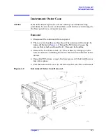
2. There are two handles on the sides of the instrument that must be
taken off. Refer to
. Using the T-20 driver, loosen the
screws that attach each handle
(1)
. Remove the handles.
3. Remove the four bottom feet
(2)
. This is done by lifting up on the
tabs on the feet, and sliding the feet in the direction indicated by the
arrows.
4. Using the T-15 driver, remove the four screws
(3)
that hold the rear
feet
(4)
in place.
5. Pull the instrument cover
(5)
off towards the rear of the instrument.
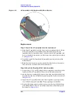
Figure 4-2
Instrument Outer Case Removal
Summary of Contents for E4406A VSA Series
Page 4: ...4 ...
Page 10: ...10 Contents ...
Page 11: ...11 1 Troubleshooting ...
Page 66: ...66 Chapter1 Troubleshooting How to Return Your Instrument for Service ...
Page 67: ...67 2 Block Diagrams ...
Page 119: ...Chapter 2 119 Block Diagrams Block Diagrams Block Diagrams ...
Page 120: ...120 Chapter2 Block Diagrams Block Diagrams ...
Page 122: ...122 Chapter2 Block Diagrams Block Diagrams ...
Page 124: ...124 Chapter2 Block Diagrams Block Diagrams ...
Page 125: ...125 3 Parts List ...
Page 164: ...164 Chapter3 Parts List Hardware ...
Page 165: ...165 4 Assembly Replacement ...
Page 169: ......
Page 170: ...170 Chapter4 Assembly Replacement Removal and Replacement Procedures ...
Page 227: ...Chapter 4 227 Assembly Replacement Front Frame Subassemblies Figure 4 39 Keypad Parts ...
Page 231: ...231 5 Post Repair Procedures ...
Page 262: ...262 Chapter5 Post Repair Procedures Automated Adjustments ...

