Chapter 4
175
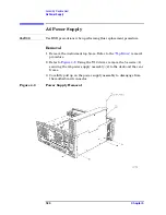
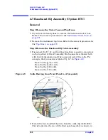
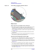
Assembly Replacement
Front Frame
Front Frame
For most service situations, the front frame assembly can be “dropped”
from the deck without disconnecting any cables. Refer to the section
. To completely remove the front frame,
continue with the
section.
CAUTION
Use ESD precautions when performing this replacement procedure.
Drop the Front Frame
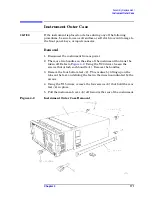
1. Remove the instrument outer case. Refer to the
removal procedure.
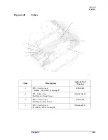
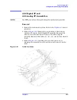
2. Refer to
. Using the T-10 driver, remove the 6 screws
(1)
that attach the front frame assembly
(2)
to the deck.
3. Pull the front frame off of the deck until it is disengaged from the
disc drive.
4. At this point, the front frame can be placed flat on the bench for
service while still attached to the instrument. If you want to
completely remove the front frame, continue with the
section.
Removal
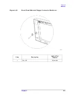
1. Using a 9/16” socket drive, remove the nut securing the
External
Trigger Input
BNC connector. Take care to not scratch the front dress
panel. A 9/16” deep-socket nut driver, part number 8720-0008, is
available from Agilent Technologies.
2. Refer to
. Disconnect the ribbon cable
(3)
from the A3
front panel interface board. Pull the coaxial cable
(4)
from the front
frame and unclip from the two cable clamps.
3. Lift the front frame assembly away from the deck.
Summary of Contents for E4406A VSA Series
Page 4: ...4 ...
Page 10: ...10 Contents ...
Page 11: ...11 1 Troubleshooting ...
Page 66: ...66 Chapter1 Troubleshooting How to Return Your Instrument for Service ...
Page 67: ...67 2 Block Diagrams ...
Page 119: ...Chapter 2 119 Block Diagrams Block Diagrams Block Diagrams ...
Page 120: ...120 Chapter2 Block Diagrams Block Diagrams ...
Page 122: ...122 Chapter2 Block Diagrams Block Diagrams ...
Page 124: ...124 Chapter2 Block Diagrams Block Diagrams ...
Page 125: ...125 3 Parts List ...
Page 164: ...164 Chapter3 Parts List Hardware ...
Page 165: ...165 4 Assembly Replacement ...
Page 169: ......
Page 170: ...170 Chapter4 Assembly Replacement Removal and Replacement Procedures ...
Page 227: ...Chapter 4 227 Assembly Replacement Front Frame Subassemblies Figure 4 39 Keypad Parts ...
Page 231: ...231 5 Post Repair Procedures ...
Page 262: ...262 Chapter5 Post Repair Procedures Automated Adjustments ...

