182
Chapter 4
Assembly Replacement
A7 Baseband I/Q Assembly (Option B7C)
A7 Baseband I/Q Assembly (Option B7C)
Removal
Step 1 Remove the Outer Case and Top Brace
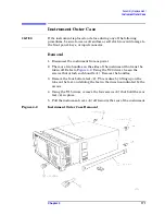
1. If you haven’t already done so, remove the instrument outer case.
Refer to the removal procedure for the
.
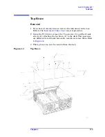
2. Remove the instrument top brace. Refer to the removal procedure for
the
Step 2 Remove the Baseband I/Q Cable Assembly
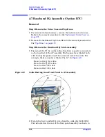
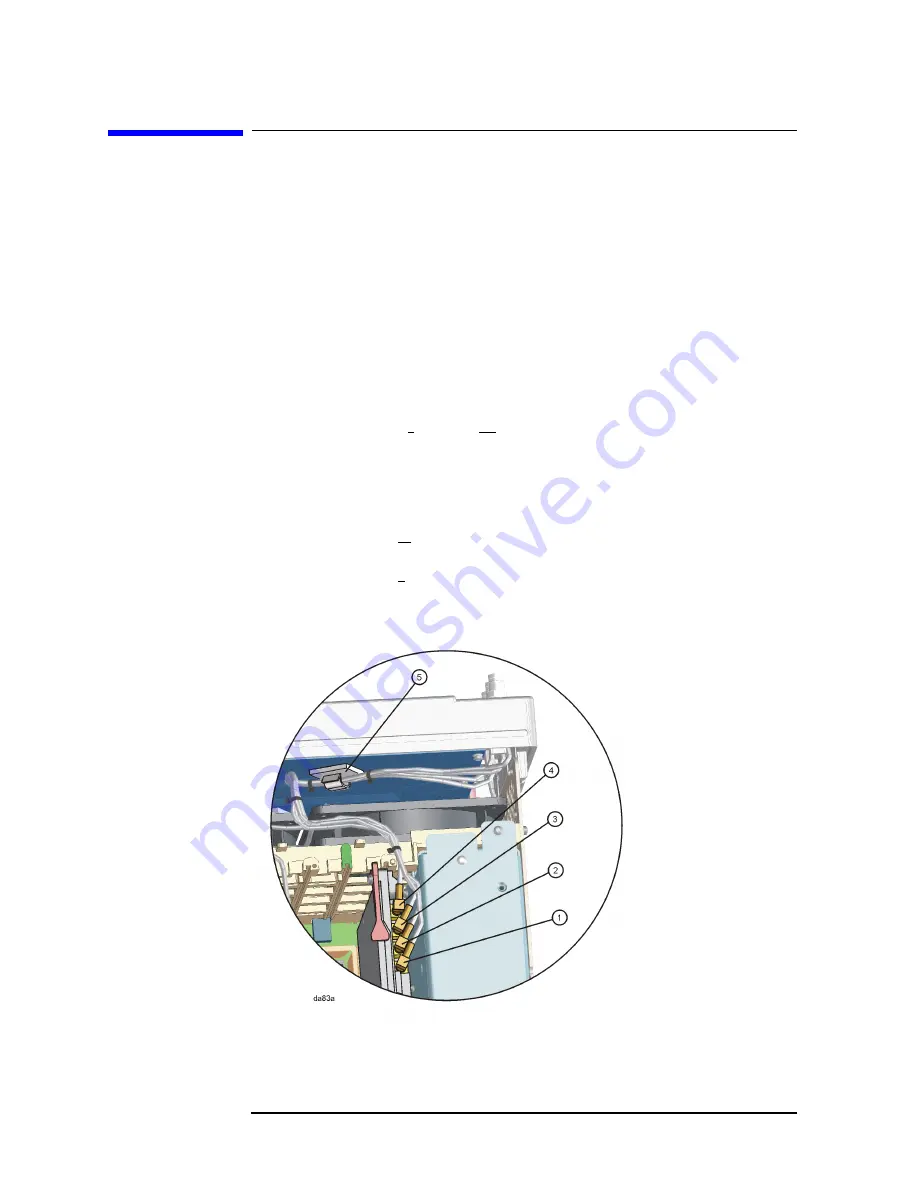
1. Disconnect the I, I, Q, and Q cables from their respective connectors
on the top-front of the A7 assembly. Each connector is labeled both
with the I/Q designation and the numerical code of the cable. For
example, the Q connector is labeled “Q, 14”. In
:
Item 1 is the Q (14) cable.
Item 2 is the Q (15) cable.
Item 3 is the I (12) cable.
Item 4 is the I (13) cable.
Figure 4-9
Cable Routing from Front Panel to A7 Assembly
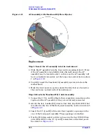
2. Detach the four, bundled I/Q wires from the cable clip (1400-3014)
that is located on the rear of the front panel assembly, as shown in
Summary of Contents for E4406A VSA Series
Page 4: ...4 ...
Page 10: ...10 Contents ...
Page 11: ...11 1 Troubleshooting ...
Page 66: ...66 Chapter1 Troubleshooting How to Return Your Instrument for Service ...
Page 67: ...67 2 Block Diagrams ...
Page 119: ...Chapter 2 119 Block Diagrams Block Diagrams Block Diagrams ...
Page 120: ...120 Chapter2 Block Diagrams Block Diagrams ...
Page 122: ...122 Chapter2 Block Diagrams Block Diagrams ...
Page 124: ...124 Chapter2 Block Diagrams Block Diagrams ...
Page 125: ...125 3 Parts List ...
Page 164: ...164 Chapter3 Parts List Hardware ...
Page 165: ...165 4 Assembly Replacement ...
Page 169: ......
Page 170: ...170 Chapter4 Assembly Replacement Removal and Replacement Procedures ...
Page 227: ...Chapter 4 227 Assembly Replacement Front Frame Subassemblies Figure 4 39 Keypad Parts ...
Page 231: ...231 5 Post Repair Procedures ...
Page 262: ...262 Chapter5 Post Repair Procedures Automated Adjustments ...


