212
Chapter 4
Assembly Replacement
Center Web Cables W9, W11, and W12
Center Web Cables W9, W11, and W12
CAUTION
Use ESD precautions when performing this replacement procedure.
NOTE
When ordering a replacement center web cable, W9, W11, or W12, it is
necessary to also order the cable retainer and snap ring. Refer to
for the part numbers.
Removal and Replacement
1. Remove the instrument top brace. Refer to the
removal
procedure.
2. Remove the A10 and A12 assemblies. Refer to the
removal procedure.
3. Remove the A7 assembly (if installed). Refer to the
removal procedure.
4. Remove the A17, A18, and A19 assemblies. Refer to the
A18 Reference, and A19 Synthesizer Assemblies”
removal
procedure.
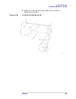
5. Refer to
. To remove a cable from the center web, it is
necessary to first remove the snap ring
(1)
. Use the snap ring tool to
separate the snap ring and remove it from the cable retainer.
6. Once the snap ring is removed, the cable and cable
retainer
(2)
can be pulled away from the center web. To remove the
21.4 MHz cable (W12), it is necessary to disconnect the cable from
the A10 analog IF assembly. To remove the RF input cable (W9), it is
also necessary to disconnect the cable from the input
connector/attenuator assembly. Refer to the
removal procedure.
7. When replacing a cable into the center web, first secure the cable
retainer in the proper place in the center web with the snap ring.
The cable end can now be located in the cable retainer and snapped
into place. Refer to
for the proper placement of cables.
8. Replace the A10 and the A12 assemblies. Refer to the
IF and A12 Analog IF Assemblies”
replacement procedure.
9. Replace the A7 assembly (if installed). Refer to the
replacement procedure.
10.Replace the A17, A18, and A19 assemblies. Refer to the
A18 Reference, and A19 Synthesizer Assemblies”
replacement
procedure.
Summary of Contents for E4406A VSA Series
Page 4: ...4 ...
Page 10: ...10 Contents ...
Page 11: ...11 1 Troubleshooting ...
Page 66: ...66 Chapter1 Troubleshooting How to Return Your Instrument for Service ...
Page 67: ...67 2 Block Diagrams ...
Page 119: ...Chapter 2 119 Block Diagrams Block Diagrams Block Diagrams ...
Page 120: ...120 Chapter2 Block Diagrams Block Diagrams ...
Page 122: ...122 Chapter2 Block Diagrams Block Diagrams ...
Page 124: ...124 Chapter2 Block Diagrams Block Diagrams ...
Page 125: ...125 3 Parts List ...
Page 164: ...164 Chapter3 Parts List Hardware ...
Page 165: ...165 4 Assembly Replacement ...
Page 169: ......
Page 170: ...170 Chapter4 Assembly Replacement Removal and Replacement Procedures ...
Page 227: ...Chapter 4 227 Assembly Replacement Front Frame Subassemblies Figure 4 39 Keypad Parts ...
Page 231: ...231 5 Post Repair Procedures ...
Page 262: ...262 Chapter5 Post Repair Procedures Automated Adjustments ...

