222
Chapter 4
Assembly Replacement
Front Frame Subassemblies
Backlight Removal/Replacement
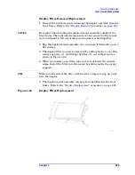
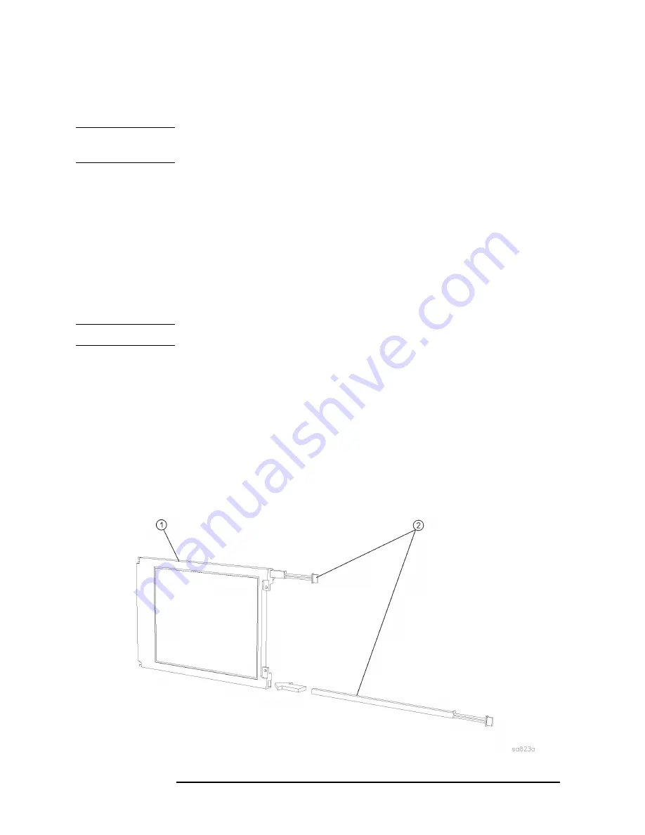
There are two backlight assemblies installed in the flat panel display.
NOTE
The backlight lamps should be replaced as a pair, even if only one lamp
is bad. The other one might fail shortly.
1. Refer to
. Unplug the backlight cables
(5)
from the
backlight connectors
(6)
2. Lift up on the side of the display mount with the backlight
connectors coming out. It is not necessary to completely remove the
display mount from the front frame to change the backlights.
3.
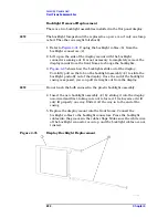
shows how the backlights slide out of the display.
Carefully pull on the tab on the backlight assembly
(2)
to slide the
backlight partially out of the display. Once the end of the backlight
casing is exposed, you can pull it straight out from the display.
NOTE
Do not touch the bulb encased in the plastic backlight assembly.
4. Insert the new backlight assembly
(2)
by sliding it into the display,
non-wired end first, taking care not to force it. It is keyed so it will
only fit properly one way. Slide it all the way in to the end of the
casing.
5. Replace the display mount into the front frame. Connect the
backlight cables to the backlight connectors. Press the backlight
cables into the grooves in the rubber flaps. Make sure the white wire
of the backlight connector is on top, and the backlight cables are not
twisted.
Figure 4-35
Display Backlight Replacement
Summary of Contents for E4406A VSA Series
Page 4: ...4 ...
Page 10: ...10 Contents ...
Page 11: ...11 1 Troubleshooting ...
Page 66: ...66 Chapter1 Troubleshooting How to Return Your Instrument for Service ...
Page 67: ...67 2 Block Diagrams ...
Page 119: ...Chapter 2 119 Block Diagrams Block Diagrams Block Diagrams ...
Page 120: ...120 Chapter2 Block Diagrams Block Diagrams ...
Page 122: ...122 Chapter2 Block Diagrams Block Diagrams ...
Page 124: ...124 Chapter2 Block Diagrams Block Diagrams ...
Page 125: ...125 3 Parts List ...
Page 164: ...164 Chapter3 Parts List Hardware ...
Page 165: ...165 4 Assembly Replacement ...
Page 169: ......
Page 170: ...170 Chapter4 Assembly Replacement Removal and Replacement Procedures ...
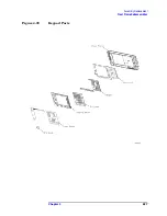
Page 227: ...Chapter 4 227 Assembly Replacement Front Frame Subassemblies Figure 4 39 Keypad Parts ...
Page 231: ...231 5 Post Repair Procedures ...
Page 262: ...262 Chapter5 Post Repair Procedures Automated Adjustments ...


