234
Chapter 5
Post-Repair Procedures
Post-Repair Procedures
Post-Repair Procedures
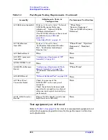
lists the adjustments, tests, configuration procedures, and
performance verification tests needed after an assembly replacement.
Adjustments and performance verification tests are available in the
Agilent N7812A E4406A Calibration Application Software
.
After an assembly is replaced, find the assembly that has been replaced
in the left-hand column, and then perform the adjustment, test, or
configuration procedure shown in the adjustment column. After
successfully completing the necessary adjustment, test, or configuration
procedure, verify that the instrument meets specifications by running
the performance verification test or tests listed.
NOTE
Refer to instrument specifications (or the software) for information on
instrument warm-up before performing any of the procedures listed in
this chapter.
Table 5-1
Post-Repair Testing Requirements
Assembly
Adjustments, Tests, &
Configuration
Performance Verification
A1 Keyboard
Front Panel test. Refer to
None
A2 Flat Panel Display
Ensure that the display quality is
satisfactory. There should be no light
or dark lines or pixel “triplets”.
None
A3 Front Panel
Interface Assembly
Front Panel test.
Ensure that the display quality and
brightness are satisfactory.
Ensure that the green “Power On”
LED and yellow ‘Standby” LED light
properly.
None
A4 Disk Drive Assembly
Save data to a disk by:
1. Inserting a blank DOS formatted
disk into the disk drive.
2. Press
Print Setup
key.
3. Select print to file.
4. Select Print Location Floppy.
5. Press
key and ensure disk
drive light comes on indicating
that data is being saved to disk.
None
Summary of Contents for E4406A VSA Series
Page 4: ...4 ...
Page 10: ...10 Contents ...
Page 11: ...11 1 Troubleshooting ...
Page 66: ...66 Chapter1 Troubleshooting How to Return Your Instrument for Service ...
Page 67: ...67 2 Block Diagrams ...
Page 119: ...Chapter 2 119 Block Diagrams Block Diagrams Block Diagrams ...
Page 120: ...120 Chapter2 Block Diagrams Block Diagrams ...
Page 122: ...122 Chapter2 Block Diagrams Block Diagrams ...
Page 124: ...124 Chapter2 Block Diagrams Block Diagrams ...
Page 125: ...125 3 Parts List ...
Page 164: ...164 Chapter3 Parts List Hardware ...
Page 165: ...165 4 Assembly Replacement ...
Page 169: ......
Page 170: ...170 Chapter4 Assembly Replacement Removal and Replacement Procedures ...
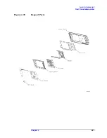
Page 227: ...Chapter 4 227 Assembly Replacement Front Frame Subassemblies Figure 4 39 Keypad Parts ...
Page 231: ...231 5 Post Repair Procedures ...
Page 262: ...262 Chapter5 Post Repair Procedures Automated Adjustments ...

