254
Chapter 5
Post-Repair Procedures
Burst Trigger Check
Burst Trigger Check
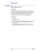
Description
The Burst Trigger Check verifies the ability of the instrument to sync
on the burst trigger signal. The instrument internal IF Alignment
signal is activated and configured to provide a pulse train. The pulses
are displayed on the RF Envelope window, and will appear as an
unsynchronized signal. When the RF Burst trigger function is
activated, the RF train will sync on the burst trigger signal.
Procedure
1. Press
Preset
.
2. Press
MODE
and
Service
.
3. Press
Input
,
Input Port IF Align
,
IF Align Signal
,
Signal Type
, and
Pulse
.
The unsynchronized pulse train will be displayed on the RF
Envelope window.
4. Press
Meas Setup
,
Trigger Source
, and
RF Burst
. The pulse train,
displayed on the RF Envelope window, will now be synchronized.
Summary of Contents for E4406A VSA Series
Page 4: ...4 ...
Page 10: ...10 Contents ...
Page 11: ...11 1 Troubleshooting ...
Page 66: ...66 Chapter1 Troubleshooting How to Return Your Instrument for Service ...
Page 67: ...67 2 Block Diagrams ...
Page 119: ...Chapter 2 119 Block Diagrams Block Diagrams Block Diagrams ...
Page 120: ...120 Chapter2 Block Diagrams Block Diagrams ...
Page 122: ...122 Chapter2 Block Diagrams Block Diagrams ...
Page 124: ...124 Chapter2 Block Diagrams Block Diagrams ...
Page 125: ...125 3 Parts List ...
Page 164: ...164 Chapter3 Parts List Hardware ...
Page 165: ...165 4 Assembly Replacement ...
Page 169: ......
Page 170: ...170 Chapter4 Assembly Replacement Removal and Replacement Procedures ...
Page 227: ...Chapter 4 227 Assembly Replacement Front Frame Subassemblies Figure 4 39 Keypad Parts ...
Page 231: ...231 5 Post Repair Procedures ...
Page 262: ...262 Chapter5 Post Repair Procedures Automated Adjustments ...


