Chapter 5
259
Post-Repair Procedures
Front Panel Test
Front Panel Test
Purpose
The front panel test checks the functionality of the instrument front
panel keys and the RPG knob.
Test Setup
Press
Mode
,
More, Service, More, Front Panel Test
. Once the
Front Panel
Test
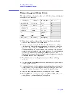
key is pressed you will see a display with three columns appear on
the screen. The entries on the left side of each column describe a key.
On the right side of each entry you will see a
0
.
The front panel test requires you to press each of the front panel keys
(in any order, with the exception of the
ESC
key, which
must
be pressed
last), and to turn the RPG knob. The first time you press a key a
1
will
replace the
0
that originally appeared to the right of the key column.
Each additional instance of pressing a given key will result in an
increment to the number listed in the column to the right of the key
description. For example if you press the
Zoom
key four times, you will
see a
4
to the right of the
Zoom
entry.
Rotating the RPG knob will result in a rapidly incrementing, or
decrementing value appearing in the column to the right of the
RPG
Knob
entry. Rotate the RPG knob clockwise and counter-clockwise. You
will see negative or positive values appear, in ascending or descending
order, depending on the direction you have turned the RPG knob.
Note that the two step keys (the up and down arrow keys) are described
as the
Rpg Dn
and
Rpg Up
keys.
The
ESC
key must be pressed only after all other keys have been
pressed and the RPG knob has been rotated; pressing the
ESC
key will
cause the front panel test to be cancelled.
Summary of Contents for E4406A VSA Series
Page 4: ...4 ...
Page 10: ...10 Contents ...
Page 11: ...11 1 Troubleshooting ...
Page 66: ...66 Chapter1 Troubleshooting How to Return Your Instrument for Service ...
Page 67: ...67 2 Block Diagrams ...
Page 119: ...Chapter 2 119 Block Diagrams Block Diagrams Block Diagrams ...
Page 120: ...120 Chapter2 Block Diagrams Block Diagrams ...
Page 122: ...122 Chapter2 Block Diagrams Block Diagrams ...
Page 124: ...124 Chapter2 Block Diagrams Block Diagrams ...
Page 125: ...125 3 Parts List ...
Page 164: ...164 Chapter3 Parts List Hardware ...
Page 165: ...165 4 Assembly Replacement ...
Page 169: ......
Page 170: ...170 Chapter4 Assembly Replacement Removal and Replacement Procedures ...
Page 227: ...Chapter 4 227 Assembly Replacement Front Frame Subassemblies Figure 4 39 Keypad Parts ...
Page 231: ...231 5 Post Repair Procedures ...
Page 262: ...262 Chapter5 Post Repair Procedures Automated Adjustments ...


