26
Chapter 1
Troubleshooting
Troubleshooting an Inoperative Instrument
Troubleshooting an Inoperative Instrument
When the instrument appears to be dead (no display and no fans), there
is often little evidence that points directly to the cause. This section
provides steps and solutions to typical failure modes relating to an
inoperative instrument.
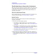
Check the Instrument Setup
Before troubleshooting the instrument, ensure that it has been set up
correctly. Perform the steps in
.
Initial Checks
Perform the following initial checks when first troubleshooting an
inoperative instrument.
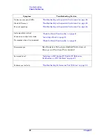
1. Check the instrument display and fans.
a. If the display is dark and the fans are not running, suspect a
power supply or CPU problem. Refer to the
b. If the display is dark but the fans are running, suspect either an
LCD problem, or a problem with the CPU boot sequence. Refer to
"Troubleshooting LCD Display Problems" on page 28
c. If the display looks good but the fans are not running, refer to
the Fans Are Not Operating" on page 27
.
2. If the instrument appears to abort the boot process, experiences a
failure during the self-diagnostic tests, or there is no response when
a front panel key is pressed, refer to
"Check for Basic Functionality"
.
Summary of Contents for E4406A VSA Series
Page 4: ...4 ...
Page 10: ...10 Contents ...
Page 11: ...11 1 Troubleshooting ...
Page 66: ...66 Chapter1 Troubleshooting How to Return Your Instrument for Service ...
Page 67: ...67 2 Block Diagrams ...
Page 119: ...Chapter 2 119 Block Diagrams Block Diagrams Block Diagrams ...
Page 120: ...120 Chapter2 Block Diagrams Block Diagrams ...
Page 122: ...122 Chapter2 Block Diagrams Block Diagrams ...
Page 124: ...124 Chapter2 Block Diagrams Block Diagrams ...
Page 125: ...125 3 Parts List ...
Page 164: ...164 Chapter3 Parts List Hardware ...
Page 165: ...165 4 Assembly Replacement ...
Page 169: ......
Page 170: ...170 Chapter4 Assembly Replacement Removal and Replacement Procedures ...
Page 227: ...Chapter 4 227 Assembly Replacement Front Frame Subassemblies Figure 4 39 Keypad Parts ...
Page 231: ...231 5 Post Repair Procedures ...
Page 262: ...262 Chapter5 Post Repair Procedures Automated Adjustments ...

