Chapter 1
33
Troubleshooting
Auto-Align Tests
NOTE
Additional auto-alignment procedures are performed for instruments
equipped with base band I/Q inputs (Option B7C).
Nominal System Gain
With the analog IF preFilter OFF and IF BW set to 5 kHz, alignment is done using the
50 MHz ref cal signal to measure the residual amplitude error (offset) at the center
frequency in default (reference) settings (eg. 10 dB atten). This error is used to compensate
acquisition data whenever there is an “absence” of a valid current system gain alignment; in
other words, this becomes the “default” gain correction to fall back on.
321 MHz Amplitude
The 321 MHz cal osc signal from the A17 RF assembly is used for many internal
alignments. This alignment merely calibrates the amplitude control dac for this signal, for
use by the other alignments when necessary to set fairly accurate amplitude levels.
LC Prefilter Wide
This alignment is run once for WIDE (BW>1.2 MHz) and once for NARROW. The 321 MHz
Comb cal osc is used to align BW and CF for the analog IF LC path. Coefficients are
generated for a curve that maps BW-Dac to requested BW. Another curve is generated
which represents Gain vs BW. Both these curves are then used during Prefilter and IF gain
setup during a measurement.
LC Prefilter Narrow
See description for LC Prefilter Wide.
XTAL Prefilter Wide
This alignment is run once for WIDE (BW>20 kHz) and once for NARROW. The 321 MHz
Comb cal osc is used to align BW, SYM, & CF for the analog IF XTAL path. Coefficients are
generated for a curve that maps BW-Dac to requested BW. Another curve is generated
which represents Gain vs BW. Both these curves are then used during Prefilter and IF gain
setup during a measurement.
XTAL Prefilter Narrow
See description for XTAL Prefilter Wide.
ADC Autorange
The ADC autoranging subsystem has several hardware components that need to be setup.
This alignment takes care of 3 dacs: 2 dacs on the A10 digital IF assembly that set the
positive and negative thresholds for range switches; and 1 dac on the A12 analog IF
assembly that sets the GAIN of the autoranging detector signal. It also generates 4 gain
values to be used for 4 possible measurement setups. The 4 setups cover the on/off positions
of dither and analog IF post-filter. This is necessary since these positions produce different
relative signal levels between the main path and the autorange path.
Attenuator Steps
Align the relative error of each attenuator step at 50 MHz. The 10 dB attenuator setting is
considered the reference, with 0 dB error by default. A CW signal is injected at 50 MHz and
each attenuator step is measured to yield an error relative to the step’s assumed value (for
example: an attenuator setting of 21 is expected to produce 21 dB of attenuation... if it
produces 21.12, the error is 0.12 dB).
Trigger Delays
This alignment currently is used ONLY for delay compensation within the CDMA
personality for measurements which synchronize to an “even second clock”. This alignment
measures the delay of the IF path for the one particular setup used for this CDMA
application.
Measure Comb Teeth
The amplitude of the internal 50 MHz reference is compared to the amplitude of the 20
comb teeth (used during IF flatness alignment) by tuning the LO. If the resulting
comparison is greater than a particular amount, the alignment fails. Mainly used for wide
span comb settings that require measurements in order to achieve flatness down to 0.1 or
0.2 dB in the 10 MHz span.
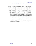
Table 1-3
Sequence for Auto-Align Procedures
Procedure Name
Procedure Description
Summary of Contents for E4406A VSA Series
Page 4: ...4 ...
Page 10: ...10 Contents ...
Page 11: ...11 1 Troubleshooting ...
Page 66: ...66 Chapter1 Troubleshooting How to Return Your Instrument for Service ...
Page 67: ...67 2 Block Diagrams ...
Page 119: ...Chapter 2 119 Block Diagrams Block Diagrams Block Diagrams ...
Page 120: ...120 Chapter2 Block Diagrams Block Diagrams ...
Page 122: ...122 Chapter2 Block Diagrams Block Diagrams ...
Page 124: ...124 Chapter2 Block Diagrams Block Diagrams ...
Page 125: ...125 3 Parts List ...
Page 164: ...164 Chapter3 Parts List Hardware ...
Page 165: ...165 4 Assembly Replacement ...
Page 169: ......
Page 170: ...170 Chapter4 Assembly Replacement Removal and Replacement Procedures ...
Page 227: ...Chapter 4 227 Assembly Replacement Front Frame Subassemblies Figure 4 39 Keypad Parts ...
Page 231: ...231 5 Post Repair Procedures ...
Page 262: ...262 Chapter5 Post Repair Procedures Automated Adjustments ...


