Chapter 1
43
Troubleshooting
Isolating an RF, Analog IF, Digital IF, Reference, Synthesizer, or CPU Problem
Verifying the A12 Analog IF Assembly
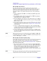
This procedure assumes the A17 RF assembly is functioning correctly.
To verify proper RF functionality, refer to the
. The A12 analog IF down-converts the 21.4 MHz
2nd IF to the 7.5 MHz 3rd and final IF. Several modes of pre- and
post-filtering occur on this board to minimize distortion products and
unwanted spurious signals.
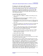
Analog IF Assembly Quick Check
1. Inject a CW signal at 50 MHz at
−
25 dBm into the RF input of the
instrument.
2. Press
Preset
on the instrument and tune to 50 MHz by pressing
Input
,
Input Port
,
RF
,
Frequency 50 MHz
.
3. Press
Input
and verify the input attenuation is set to 0 dB by viewing
the 5th softkey from the top. If it is not at 0 dB, press
Input Atten
and
enter 0 dB.
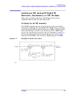
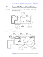
4. Disconnect the flexible gray cable (W13) going into the A10 digital IF
assembly at A10P7. Refer to
for cable
locations.
5. Connect a calibrated spectrum analyzer to the end of this flexible
cable, and measure the 7.5 MHz output from the A12 analog IF
assembly going to the A10 digital IF assembly.
6. If the A12 analog IF assembly is operating properly, the 7.5 MHz
3rd IF out of the A12 assembly will measure
−
22.5 dBm on the
calibrated spectrum analyzer.
7. Reconnect the cable to A10P7.
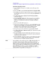
Analog IF Assembly Detailed Troubleshooting
If the quick check power level is not correct, other items can be checked
to verify the A12 analog IF assembly.
This assembly has five switchable modes of pre-filtering on the input
section of the PC board. These modes are: LC Wide, LC Narrow, Crystal
Wide, Crystal Narrow, and Bypass Mode. If one or more of these filter
modes are defective, it will cause low gain in certain instrument
settings through the system. The signal path through these pre-filters
is determined by the Pre-FFT Bandwidth, the instrument Span setting,
and the type of filtering that is selected (Gaussian or Flattop). To
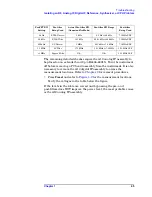
further isolate the A12 analog IF assembly performance, these various
filter modes can be selected. If the signal level on the instrument
display improves when selecting a different filter mode, the power level
problem will have been isolated to the A12 analog IF assembly.
Summary of Contents for E4406A VSA Series
Page 4: ...4 ...
Page 10: ...10 Contents ...
Page 11: ...11 1 Troubleshooting ...
Page 66: ...66 Chapter1 Troubleshooting How to Return Your Instrument for Service ...
Page 67: ...67 2 Block Diagrams ...
Page 119: ...Chapter 2 119 Block Diagrams Block Diagrams Block Diagrams ...
Page 120: ...120 Chapter2 Block Diagrams Block Diagrams ...
Page 122: ...122 Chapter2 Block Diagrams Block Diagrams ...
Page 124: ...124 Chapter2 Block Diagrams Block Diagrams ...
Page 125: ...125 3 Parts List ...
Page 164: ...164 Chapter3 Parts List Hardware ...
Page 165: ...165 4 Assembly Replacement ...
Page 169: ......
Page 170: ...170 Chapter4 Assembly Replacement Removal and Replacement Procedures ...
Page 227: ...Chapter 4 227 Assembly Replacement Front Frame Subassemblies Figure 4 39 Keypad Parts ...
Page 231: ...231 5 Post Repair Procedures ...
Page 262: ...262 Chapter5 Post Repair Procedures Automated Adjustments ...

