52
Chapter 1
Troubleshooting
Isolating an RF, Analog IF, Digital IF, Reference, Synthesizer, or CPU Problem
Verifying the A19 Synthesizer Assembly
The main function of the A19 synthesizer assembly is to provide the 1st
L.O. to the A17 RF assembly. This is accomplished by using a variable
VCO with a fundamental frequency range of 500 MHz to 1000 MHz.
This signal will be divided, bandpassed, and doubled 2 or 4 times to
achieve the correct 1st L.O. frequency. The 1st L.O. frequency depends
on the setting of the instrument’s center frequency. In most cases the
L.O. will be 321.4 MHz higher than where the center frequency of the
instrument is tuned.
For example, if the center frequency of the instrument is set to
1000 MHz, the 1st L.O. from the A19 synthesizer assembly will be
1000 MHz + 321.4 MHz or 1321.4 MHz.
Since the maximum 1st L.O. frequency is 4000 MHz, the 1st L.O. will
shift 321.4 MHz lower in frequency when the instrument is set to a
center frequency of 3678.6 MHz.
For example, if the center frequency of the instrument is set to
3678.5 MHz, the 1st L.O. is 3678.5 MHz + 321.4 MHz = 3999.9 MHz
(almost max). As soon as the instrument is set to a center frequency of
3678.6 MHz and greater the 1st L.O. will shift to
3678.6 MHz
−
321.4 MHz = 3357.2 MHz. The best location to measure
the 1st L.O. frequency and power level is when the A17 RF assembly is
placed on an extender board (p/n E4406-60042).
The A17
RF Assembly Detailed Troubleshooting
provided a process for
measuring the 1st L.O. power when the instrument was tuned to
50 MHz. Power holes or defective circuitry on the A19 synthesizer
assembly can cause low gain at other frequencies. For example, if the
instrument has low gain at 1234.5 MHz, measuring the 1st L.O. power
would be a good troubleshooting step to narrow the failure to the A19
assembly.
Synthesizer Assembly Quick Check
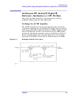
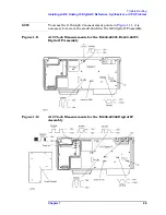
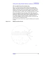
Refer to
(test point L) on
to measure the 1st L.O.
Synthesizer Assembly Detailed Troubleshooting
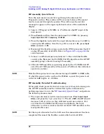
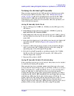
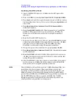
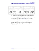
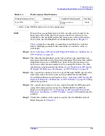
Turn the instrument on with the A19 synthesizer on an extender board
(p/n E4406-60042) and verify the following levels. If the levels are
incorrect, suspect the A19 synthesizer assembly as being defective.
Summary of Contents for E4406A VSA Series
Page 4: ...4 ...
Page 10: ...10 Contents ...
Page 11: ...11 1 Troubleshooting ...
Page 66: ...66 Chapter1 Troubleshooting How to Return Your Instrument for Service ...
Page 67: ...67 2 Block Diagrams ...
Page 119: ...Chapter 2 119 Block Diagrams Block Diagrams Block Diagrams ...
Page 120: ...120 Chapter2 Block Diagrams Block Diagrams ...
Page 122: ...122 Chapter2 Block Diagrams Block Diagrams ...
Page 124: ...124 Chapter2 Block Diagrams Block Diagrams ...
Page 125: ...125 3 Parts List ...
Page 164: ...164 Chapter3 Parts List Hardware ...
Page 165: ...165 4 Assembly Replacement ...
Page 169: ......
Page 170: ...170 Chapter4 Assembly Replacement Removal and Replacement Procedures ...
Page 227: ...Chapter 4 227 Assembly Replacement Front Frame Subassemblies Figure 4 39 Keypad Parts ...
Page 231: ...231 5 Post Repair Procedures ...
Page 262: ...262 Chapter5 Post Repair Procedures Automated Adjustments ...


