56
Chapter 1
Troubleshooting
Isolating an RF, Analog IF, Digital IF, Reference, Synthesizer, or CPU Problem
If the 30 MHz sample clock from the A12 analog IF assembly to the A10
digital IF assembly is not present, the display signal processor chip on
the digital IF assembly will not reset, causing the PCI bus to hang up
and the instrument will not boot.
To check the 30 MHz sample clock:
• Put the A10 digital IF assembly on an extender board
(E4406-60021).
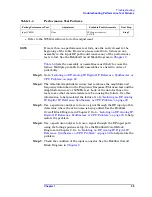
• Check A10J4 for a 30 MHz signal using an oscilloscope, as shown in
• If the signal is not present, the cause could be the A12 analog IF
assembly, or the A18 reference assembly. Go to
Reference Assembly" on page 50
to check the reference assembly.
If the boot-up process stops after the message
Processor starting
auto-boot process
appears, the firmware files on the A22A2 Flash
board may be defective. Try loading new firmware before replacing the
A22 processor or A22A2 Flash assemblies.
Look at the instrument screen and read any error messages that might
appear. The messages can give you a clue as to what is happening when
the instrument hangs up.
Battery
If you are experiencing problems with the real-time clock in your
instrument, it might be time to change the battery that is located on the
A22 processor assembly. The main purpose of the battery is to power
the real-time clock when no power is applied to the instrument. To
replace the battery, it is necessary to remove the A22 processor
assembly. Refer to
for removal procedures. The battery is
easily replaced by unclipping it from the board. Take care to install the
new battery correctly to ensure proper polarity.
WARNING
Danger of explosion if battery is incorrectly replaced. Replace
only with the same or equivalent type recommended. Discard
used batteries according to manufacturer’s instructions.
Summary of Contents for E4406A VSA Series
Page 4: ...4 ...
Page 10: ...10 Contents ...
Page 11: ...11 1 Troubleshooting ...
Page 66: ...66 Chapter1 Troubleshooting How to Return Your Instrument for Service ...
Page 67: ...67 2 Block Diagrams ...
Page 119: ...Chapter 2 119 Block Diagrams Block Diagrams Block Diagrams ...
Page 120: ...120 Chapter2 Block Diagrams Block Diagrams ...
Page 122: ...122 Chapter2 Block Diagrams Block Diagrams ...
Page 124: ...124 Chapter2 Block Diagrams Block Diagrams ...
Page 125: ...125 3 Parts List ...
Page 164: ...164 Chapter3 Parts List Hardware ...
Page 165: ...165 4 Assembly Replacement ...
Page 169: ......
Page 170: ...170 Chapter4 Assembly Replacement Removal and Replacement Procedures ...
Page 227: ...Chapter 4 227 Assembly Replacement Front Frame Subassemblies Figure 4 39 Keypad Parts ...
Page 231: ...231 5 Post Repair Procedures ...
Page 262: ...262 Chapter5 Post Repair Procedures Automated Adjustments ...


