84
Chapter 2
Block Diagrams
Miscellaneous
Miscellaneous
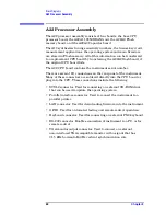
A14 Fan Control Board
Three fans are used to cool the various assemblies in the instrument.
The fan speed varies with internal instrument temperature; as the
internal temperature increases, the fan speed also increases. The front
panel power switch line that turns the power supply on and off is input
from the fan control board. An over-temperature circuit is provided that
will turn off the instrument if necessary.
A15 Daughter Board
The daughter board plugs into the A21 motherboard. It serves the
following functions:
• Supplies the 10 MHz reference signal to the A17 (RF), A19
(Synthesizer), A12 (Analog IF), and A18 (Frequency Reference
Assembly) boards. The 10 MHz reference signal comes from the A18
board.
• If the 1 to 30 MHz external reference is selected, the A15
daughterboard will output the external reference signal to the A18
board.
• Triggering signals for external equipment are input into the A15
daughter board.
A21 Motherboard
The A21 motherboard provides the following functions:
1. Provides a load to the power supply assembly for the +9 V,
−
5.2 V,
−
15 V, +5.2 V supply lines. This allows a minimum set of PC board
assemblies to be present for power supply operation. See the power
supply troubleshooting section of this manual for a list of minimum
assemblies required. This will help isolate power supply problems.
2. The on/off switch is located here.
3. Provides reg12 V and
−
12 V supplies to the processor board.
4. Provides interconnections between many assemblies.
Summary of Contents for E4406A VSA Series
Page 4: ...4 ...
Page 10: ...10 Contents ...
Page 11: ...11 1 Troubleshooting ...
Page 66: ...66 Chapter1 Troubleshooting How to Return Your Instrument for Service ...
Page 67: ...67 2 Block Diagrams ...
Page 119: ...Chapter 2 119 Block Diagrams Block Diagrams Block Diagrams ...
Page 120: ...120 Chapter2 Block Diagrams Block Diagrams ...
Page 122: ...122 Chapter2 Block Diagrams Block Diagrams ...
Page 124: ...124 Chapter2 Block Diagrams Block Diagrams ...
Page 125: ...125 3 Parts List ...
Page 164: ...164 Chapter3 Parts List Hardware ...
Page 165: ...165 4 Assembly Replacement ...
Page 169: ......
Page 170: ...170 Chapter4 Assembly Replacement Removal and Replacement Procedures ...
Page 227: ...Chapter 4 227 Assembly Replacement Front Frame Subassemblies Figure 4 39 Keypad Parts ...
Page 231: ...231 5 Post Repair Procedures ...
Page 262: ...262 Chapter5 Post Repair Procedures Automated Adjustments ...

